STM32 GPIO Peripheral Guide – CubeMX Configuration and HAL Examples
Dec 25, 2025
STM32 microcontrollers are powerful and highly flexible, but this flexibility comes at the cost of complexity. Programming an STM32 MCU often requires configuring many low-level registers for each peripheral, which can be time-consuming and error-prone, especially for beginners. To simplify this process, STM32CubeMX was introduced. It provides a graphical interface that allows developers to configure peripherals easily and automatically generates the corresponding initialization code. In this article, we use STM32CubeMX to demonstrate how to configure GPIO pins for input and output on an STM32 microcontroller. Additionally, the Hardware Abstraction Layer (HAL) provides a higher-level, portable API that hides most register-level details. It is also worth noting that STM32CubeMX is fully integrated into STM32CubeIDE, making it the standard development environment for STM32 applications.
STM32CubeIDE Installation Page
The main goal of this article is to reduce friction for beginners who want to start programming STM32 microcontrollers, allowing them to focus on concepts rather than on configuration complexity. If you are beginning with STM32 or want a solid foundation, this guide is for you. In practice, we will configure the GPIO pins in Input and output modes to interact with a button and an LED, respectively.
END Result:
This article is part of the STM32 Introduction Course, which guides beginners step by step through the fundamentals of STM32 microcontroller programming. Each chapter builds a solid foundation, starting with core concepts and gradually introducing more advanced topics.
STM32 Programming Course For Beginners
Topics to be covered:
- What is the GPIO Peripheral
- STM32 GPIO Input and Output Modes Explanation
- STM32 GPIO Pull‑Up / Pull‑Down Resistors
- Creating a project in STM32CubeIDE
- STM32 GPIO Configuration in STM32CubeMx
- Writing code to control LEDS using a button
What Is the STM32 GPIO Peripheral?
The GPIO peripheral enables the microcontroller to interact with the external world via physical pins. Each GPIO pin can:
-
Read a digital voltage level (input mode)
-
Drive a voltage level (output mode)
-
Be connected internally to a peripheral (alternate function mode: UART, SPI, I2C, timers, etc.)
-
Read an analog signal (analog mode)
In STM32 microcontrollers, GPIO pins are grouped into ports:
-
GPIOA, GPIOB, GPIOC, …
-
Each port typically has 16 pins (PA0–PA15, PB0–PB15, etc.).
Each port is controlled by its own registers and clock.
STM32 GPIO: Input and Output Modes in details
STM32 GPIO pins work with digital logic levels:
-
Logic 1 (HIGH) → voltage close to VDD (typically 3.3 V)
-
Logic 0 (LOW) → voltage close to 0 V (GND)
When a pin is configured as:
-
Output: the microcontroller actively drives the pin HIGH or LOW
-
Input: the microcontroller senses the voltage present on the pin
Voltages above a certain threshold are interpreted as HIGH (1), while voltages below another threshold are interpreted as LOW (0). In this tutorial, we will configure the basic modes of the GPIO Peripheral: input and output modes. Using these modes, we will learn to interact with a button and drive an LED.
STM32 GPIO Pull‑Up / Pull‑Down Resistors
When an input pin is left unconnected, it is said to be floating. A floating input may randomly read HIGH or LOW due to noise.
To prevent this, GPIO inputs use pull resistors:
-
Pull‑Up: forces the pin HIGH when nothing drives it
-
Pull‑Down: forces the pin LOW when nothing drives it
STM32 MCUs provide internal pull‑up and pull‑down resistors that can be enabled directly in software using CubeMX or HAL, eliminating the need for external resistors in many cases.
The classic example of the GPIO Input mode is reading the state of a button. However, using a pull-up or pull-down resistor with the button is essential. The figure below illustrates how it works. When connecting a pull-up resistor, pressing the button (closed gate) sets the voltage to 0V, whereas releasing the button (open gate) sets it to 3V. The pull-down resistor works similarly but provides opposite states. To sum up, connecting either a pull-up or pull-down resistor to the button allows us to determine the button state using the GPIO Input mode.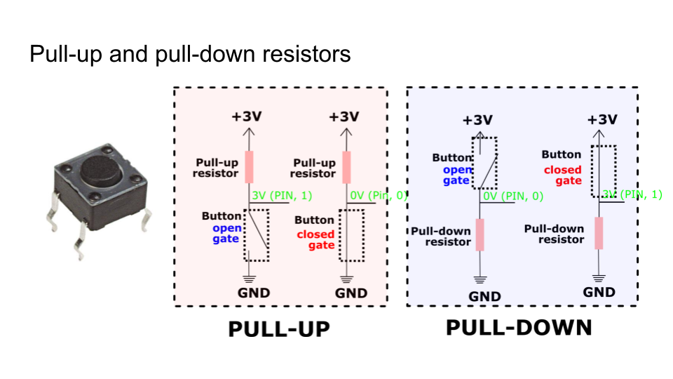
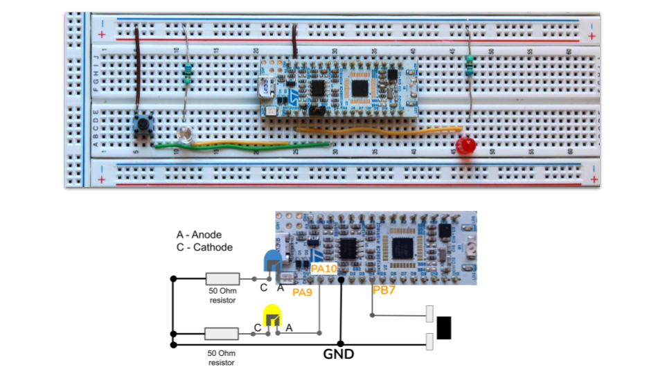
STM32 GPIO Control Hardware and Software
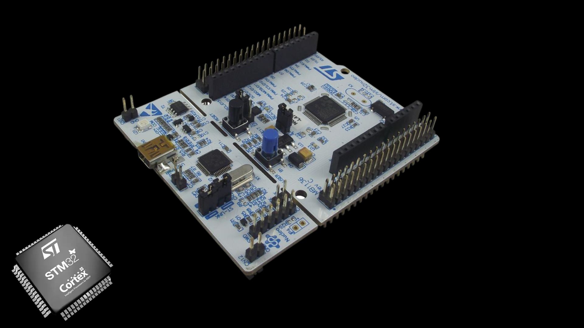
In this tutorial, I will use the Nucleo-L412kB Microcontroller Board. I will connect LEDs to PA9 and PA10 pins, and the button to PB7. I configure PB7 as a GPIO Input and PA9/PA10 as GPIO outputs. But you can use any other microcontroller you have.
I use STM32CubeIDE as a programming tool. It includes everything we need: STM32CubeMX graphical tool to configure Peripherals and Hardware Abstraction Layer (HAL) libraries.
STM32 GPIO Configuration in STM32CubeMx
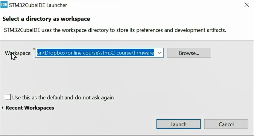
Next, let me show how to configure the GPIO peripheral using the STM32CubeMx graphical tool. First, we install the STM32CubeIDE application, which includes everything needed to program STM32 MCUs. Once the IDE is installed, launch it. It will prompt for a workspace, a folder to store our projects. You can create one and browse it when launching the IDE.
Once launched, you will be taken to the welcome page. Here, press 'Start new STM32 project.'
After, we choose the board we are using. You can search for it in the list. In my example, I am using Nucleo-L412Kb, but you must enter the board you possess.
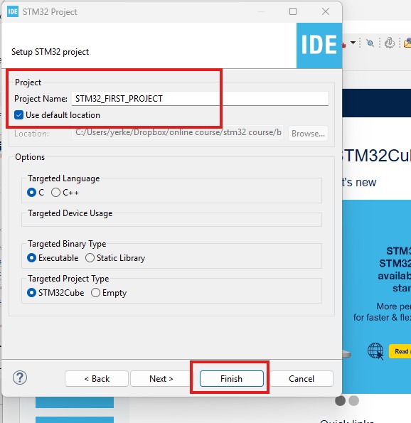
Finally, we enter the project name and press 'Finish.'
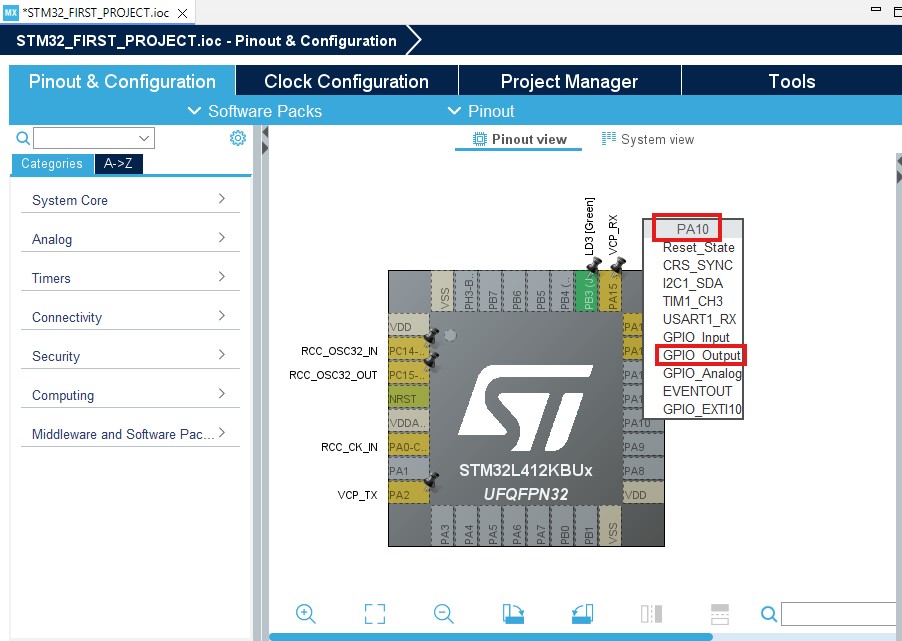
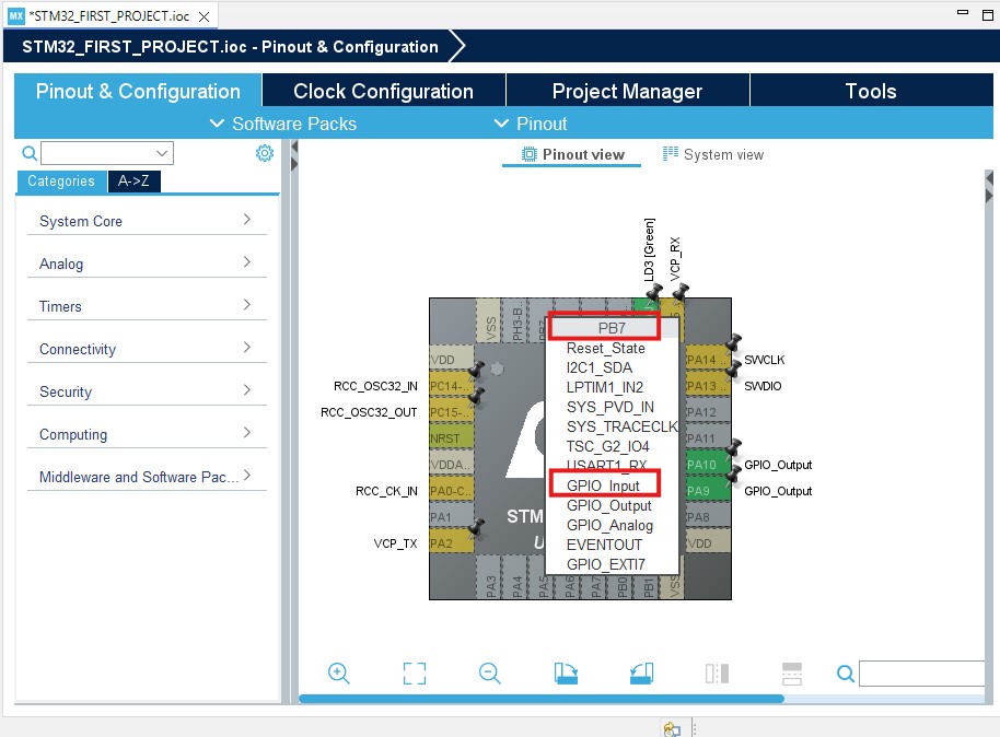
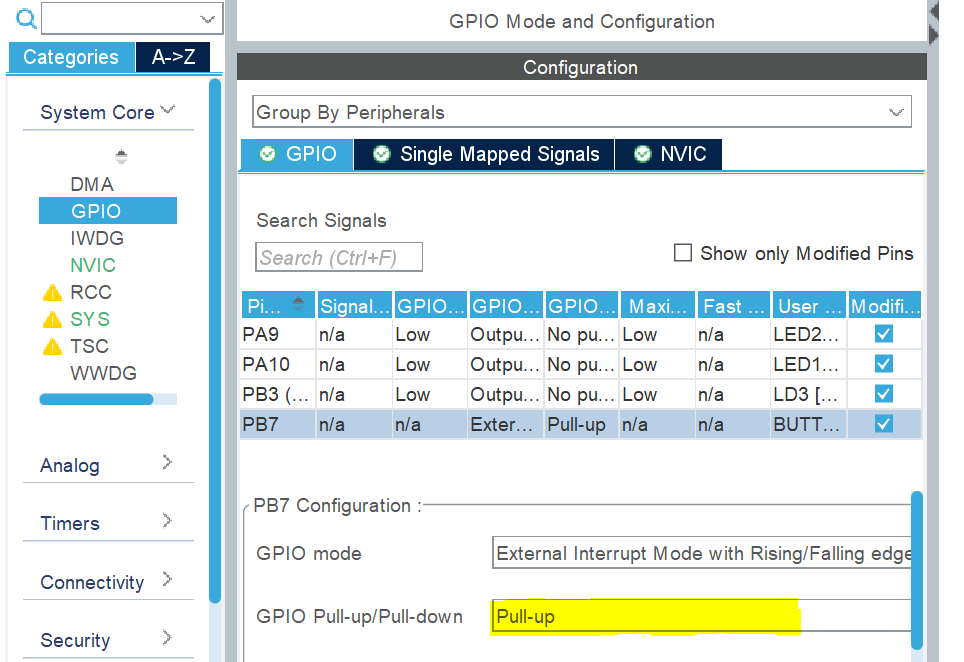
Next, I configure PA9 and PA10 as output pins, while PB7 as a GPIO input.
Next, we connect a pull-up resistor to PB7. This step is essential for reading the button's state.
Finally, we can save the final and generate the code.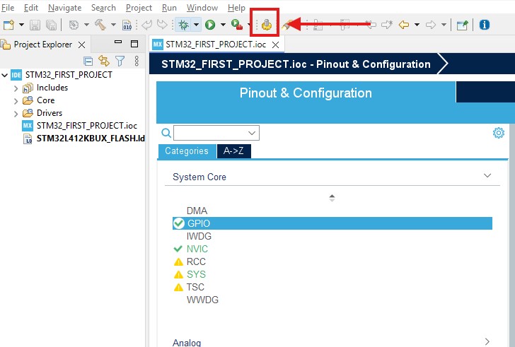
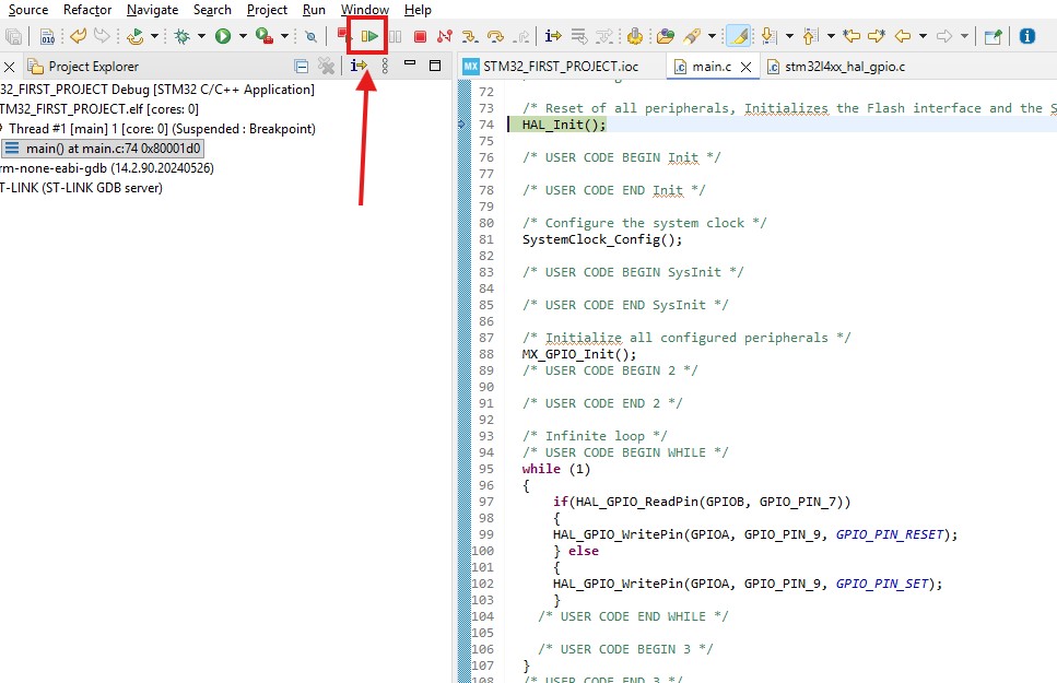
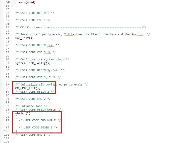
Once code generation is finished, open the main.c file and examine the main() function. You will see several initialization and configuration functions that the tool automatically generated. At the end of the function, there is an infinite while(1) loop. Any code that must run continuously during program execution should be placed within this loop.
The next step is to write code to control the GPIO output pins.
Function to Control the GPIO Output Pin:
// We use HAL_GPIO_WritePin function to control the state of the pin:HAL_GPIO_WritePin(GPIO_TypeDef\* GPIOx, uint16_t GPIO_Pin, GPIO_PinState PinState); /* It has three arguments: 1. GPIOx - Port (GPIOA, GPIOB, GPIOC, etc.) 2. GPIO_Pin - Pin(GPIO_PIN_0, GPIO_PIN_1, etc) 3. PinState - Pin state (GPIO_PIN_RESET or GPIO_PIN_SET) */
Function to read the state of the GPIO Input Pin:
// We use HAL_GPIO_ReadPin function to control the state of the pin:
HAL_GPIO_ReadPin(GPIO_TypeDef\* GPIOx, uint16_t GPIO_Pin);
/* It has two arguments:
1. GPIOx - Port (GPIOA, GPIOB, GPIOC, etc.)
2. GPIO_Pin - Pin(GPIO_PIN_0, GPIO_PIN_1, etc)
It returns the status of the pin: GPIO_PIN_RESET or GPIO_PIN_SET
*/
Using these functions, we implement logic to control the LED state when the button is pressed. We write our code within the while loop to repeatedly read the button's state.
if(HAL_GPIO_ReadPin(GPIOB, GPIO_PIN_7)){HAL_GPIO_WritePin(GPIOA, GPIO_PIN_9, GPIO_PIN_RESET);} else{HAL_GPIO_WritePin(GPIOA, GPIO_PIN_9, GPIO_PIN_SET);}
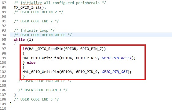
Please pay attention that we wrote this code between /* USER CODE BEGIN ... and /* USER CODE END ... comments. These comments serve as "guards" that prevent the code from being erased when updating the STM32CubeMX (.IOC) file. Next time we update the microcontroller configuration using the IOC file, the software will regenerate all files and erase any code outside the comments. Therefore, writing our code between these "guard" comments is super important.
Finally, we build (hammer) and press the debug button.
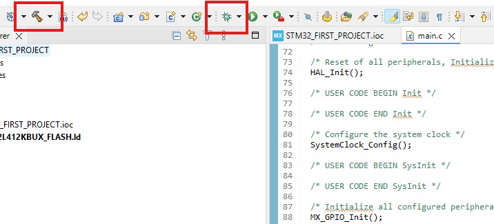
Then, if everything is correct, a debug perspective opens up.
We press the resume button and observe how pressing and releasing it changes the LED state. This is the end of the article. If you want further detailed guide on STM32 Programming, check out my STM32 Programming Course for beginners: