STM32: PWM Generation using HAL API
Oct 13, 2025
Pulse-width-modulation (PWM) is found in a wide range of electrical engineering applications, from generating sine signals to transmitting data. This article aims to introduce PWM signals in general and show how to generate them using the STM32 microcontroller by programming with the STM32CubeMX Software. In addition, I will show how the STM32 PWM signal generation works at a low level.
About PWM in general
The figure below represents the overall shape of the PWM signal. It has two main parameters: frequency (period) and duty cycle. The frequency is reverse proportional to the period of the signal. The duty cycle is the ratio between the pulse width and signal period.
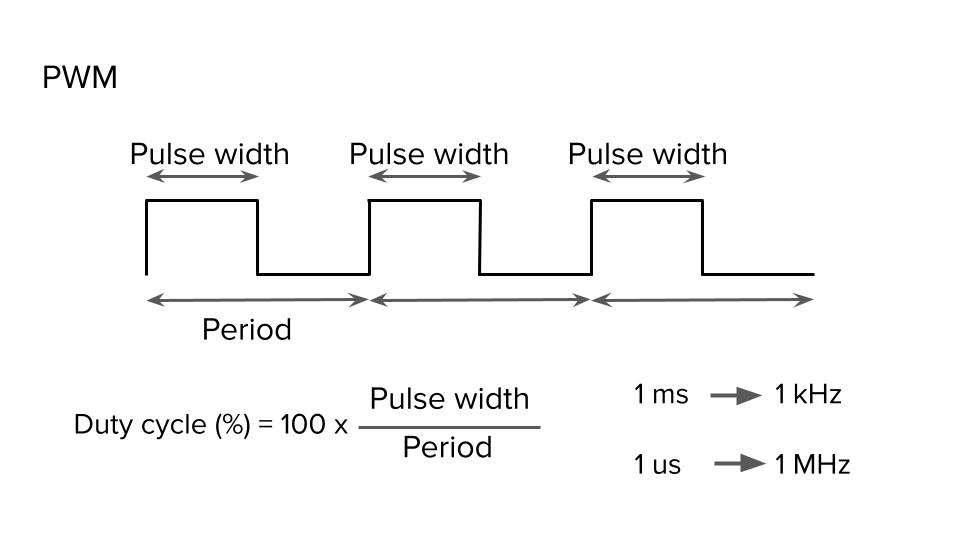
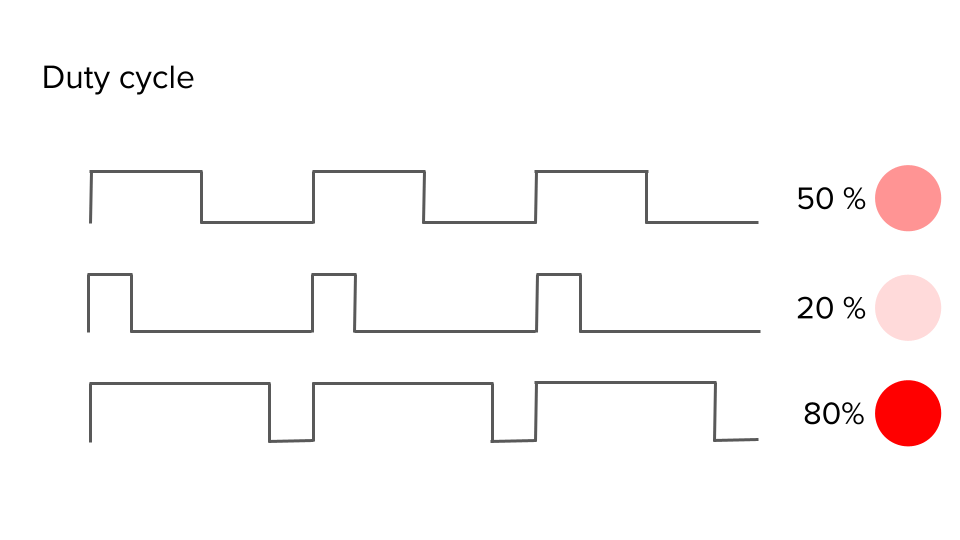
By modulating the duty cycle, we can control the signal’s power. The classic example of the PWM signal is to regulate the light level of LEDs
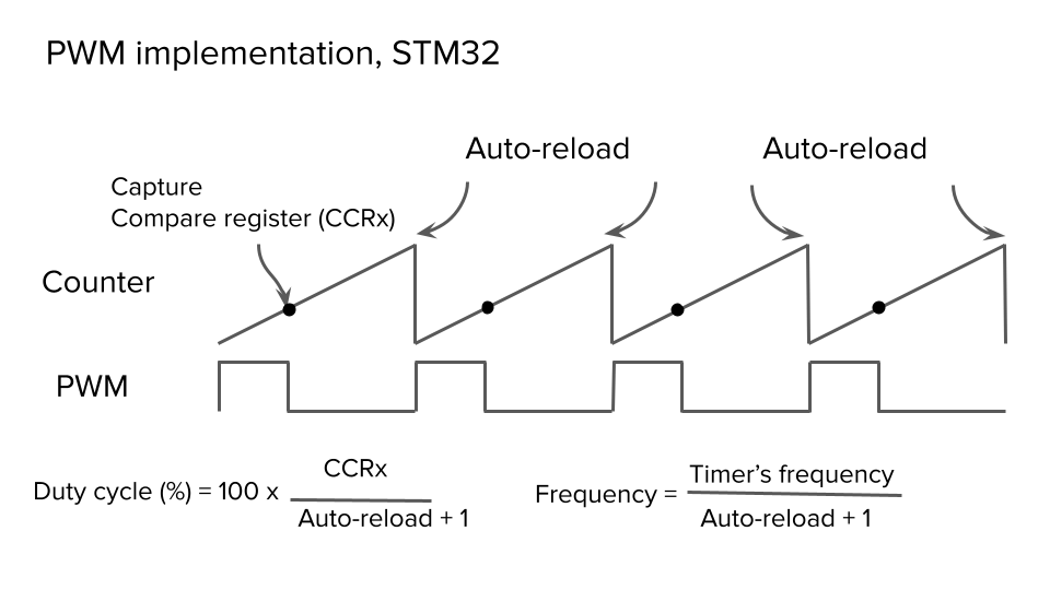
The Timer peripheral plays a central role in generating a PWM signal. Consider the figure below and discern how the microcontroller generates a PWM signal. We assume that the Timer operates in upcounting mode. The counter starts at 0 and is incremented. Unless its value exceeds the Capture Compare value (CCRxSTMicroelectronics), the PWM signal will be in a high state. When the counter reaches the CCRx value, the microcontroller resets the line. Finally, the counter reaches the auto-reload value, and the PWM signal will be high. This process will continue to generate a PWM signal with a particular frequency and duty cycle. We can control the PWM signal’s frequency by manipulating the auto-reload value. CCRx allows us to tune the duty cycle:
Generating a STM32 PWM: STM32CubeMx
I personally use the Nucleo-l412kb STM32 microcontroller board, but the article can be adapted to other boards.
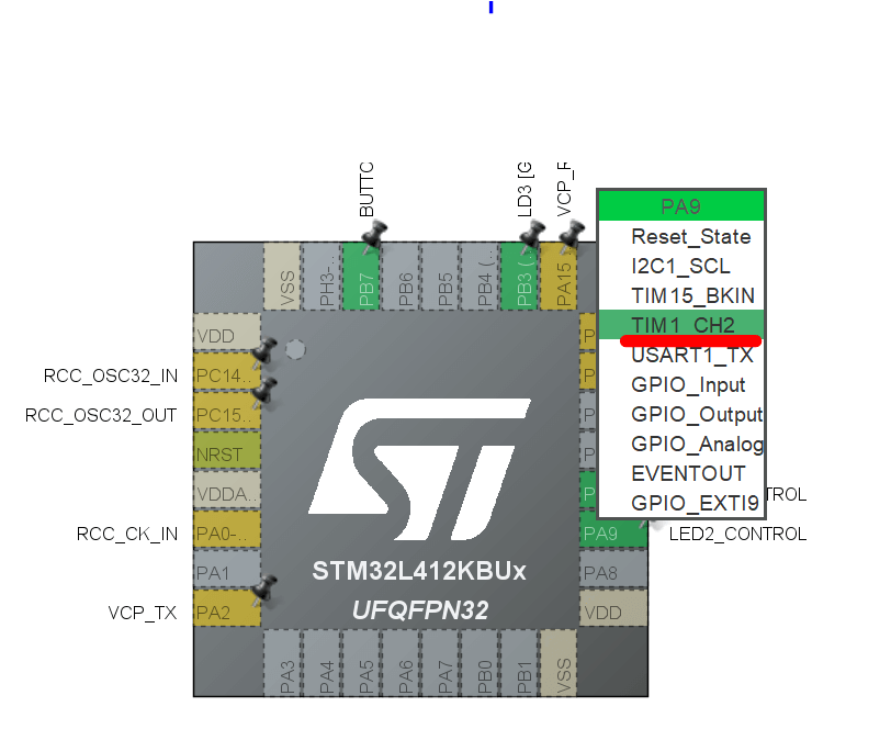
Next, we need to generate a PWM signal using STM32CubeMX. First, we change the pin configuration of PA9 and PA10 to TIM1_CH2 and TIM1_CH3, respectively, as shown in Figure below
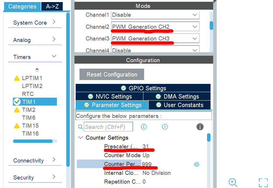
Then we enable Channels 2 and 3 of TIM1. We also set the Prescaler to 31 to obtain a 1 MHz frequency. Finally, we set the auto-reload (counter period) to 999 to achieve a 1 kHz PWM signal. Afterward, we can generate the code.
Within our code, start Timer and PWM in channels 2 and 3:
HAL_TIM_Base_Start(&htim1);
HAL_TIM_PWM_Start(&htim1, TIM_CHANNEL_2);

HAL_TIM_PWM_Start(&htim1, TIM_CHANNEL_3);
Finally, we can play with the duty cycle using the following lines:
__HAL_TIM_SET_COMPARE(&htim1, TIM_CHANNEL_2, channel2_value);

__HAL_TIM_SET_COMPARE(&htim1, TIM_CHANNEL_3, channel3_value);
Where channel2_value and channel3_value will dictate the duty cycle of the PWM signals. If we set these variables to 0, the LEDs will be entirely off. Setting 500 will provide half power, whereas setting 999 will ensure maximum light level on the LEDs.
Also, here is the video that shows the STM32 PWM Configuration in STM32CubeMX: