Self Balancing Robot: How to Build?
Oct 13, 2025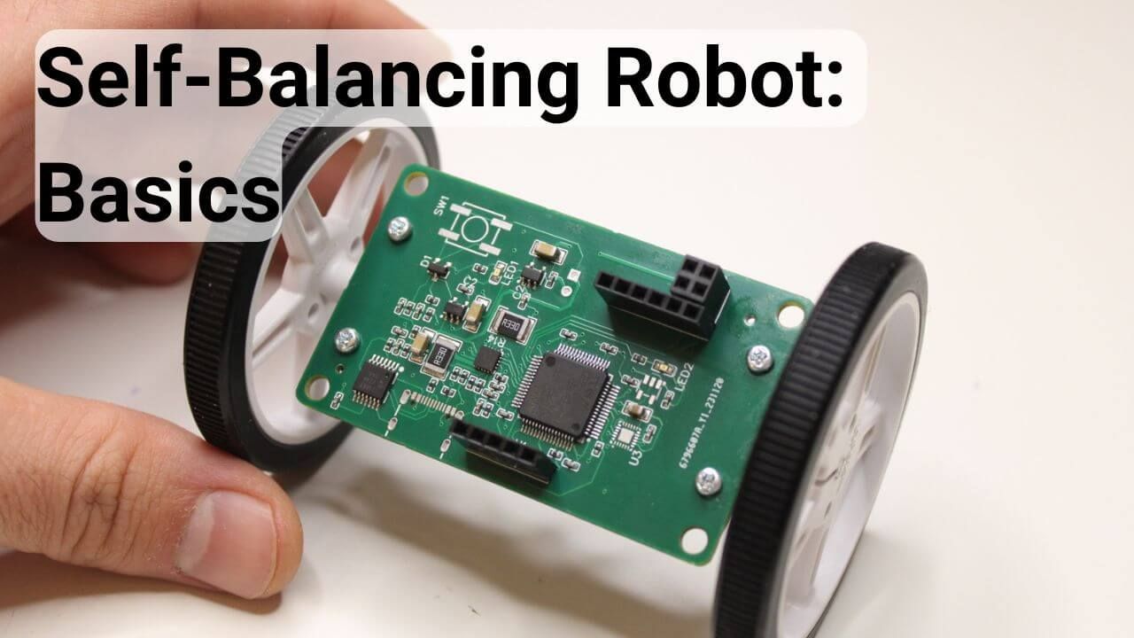
Building a self-balancing robot is an excellent starting point for anyone exploring robotics and embedded systems, as it introduces key concepts such as sensor integration, motor control, and real-time programming. This project is a microcosm of a complex robotic system, encompassing essential components like a control unit, sensors, and actuators. You’ll gain hands-on experience with PID control, sensor fusion, and motor driver integration by designing and tuning a feedback controller.
This article will guide you through the entire process, breaking it down into clear, manageable steps to help you build a stable and fully functional balancing robot. Nevertheless, I am not aiming to provide every detail of the robot's construction. Instead, I will focus on the general picture and provide valuable links for further investigation.
However, if you are interested in the complete guide to designing a balancing robot, I built the robot using an STM32 MCU. I created a comprehensive course covering the robot's control, programming, and hardware. The course is available following the link below:
Build a self-balancing robot from scratch
Self-Balancing Robot: Microcontroller
The essential component of any robot, including the self-balancing robot is a processor. Its primary purpose is to receive the sensory inputs, process them, and send motors the right signals to keep the robot balanced. In general, we have the following options:
Arduino boards. The main advantages of using the Arduino board are its accessibility and huge community. There is a high chance that you will find many guides and source codes to develop the balancing robot using Arduino boards. Check some guides I found on the web:
System-on-chip (SoC) boards, such as Raspberry Pi and BeagleBone, also have their own advantages because you can easily add a camera and other sensors to make your robot more advanced. In addition, robot development can be more manageable by writing the entire code in Python.
- https://www.youtube.com/watch?v=sTF8HTNk8Ts
- https://www.hackster.io/reductalimenitis/lotp-two-wheeled-self-balancing-robot-2b6477
STM32 Microcontrollers. These are more advanced microcontrollers than the Arduino Boards and have much higher computational power and cool peripherals. Even though it is hard to start working on them, they are primarily used in industrial applications. So, learning them opens up a world of possibilities in your career path. In addition, you can achieve very high-performance robots by running at a high frequency and utilizing advanced peripherals.
- https://www.steppeschool.com/courses/robotics-course-balancing-robot
- https://github.com/rijin113/Self_Balancing_Robot
Many more, including the ESP32, etc. There are, of course, other options, including ESP32 and Texas Instruments MCUs. You can also build a decent robot with these development boards.
- https://www.hackster.io/Arnov_Sharma_makes/mini-self-balancing-robot-64eec8
- https://github.com/Rokasbarasa1/ESP32-self-balancing-robot
- https://elexperiment.nl/2018/11/high-speed-balancing-robot-introduction/
Self-balancing Robot: Motor Control
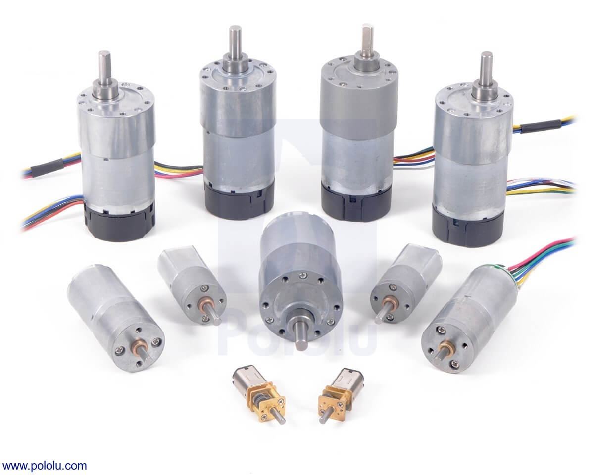
Once you choose the microcontroller, the next step is to select a motor to drive the wheels. For that, there are several options:
- Undoubtedly, DC Motors is the most affordable and easy-to-use solution for building a self-balancing robot. They are relatively inexpensive, and there are plenty of options on the market. I am sure you can get one of them in your local market. However, DC motors also introduce complexity to the robot's position control. It is vital to integrate a rotary encoder with the DC motor to avoid drift in the movement. In addition, driving the DC motor directly does not provide sufficient torque, so a gearbox is required to increase torque.
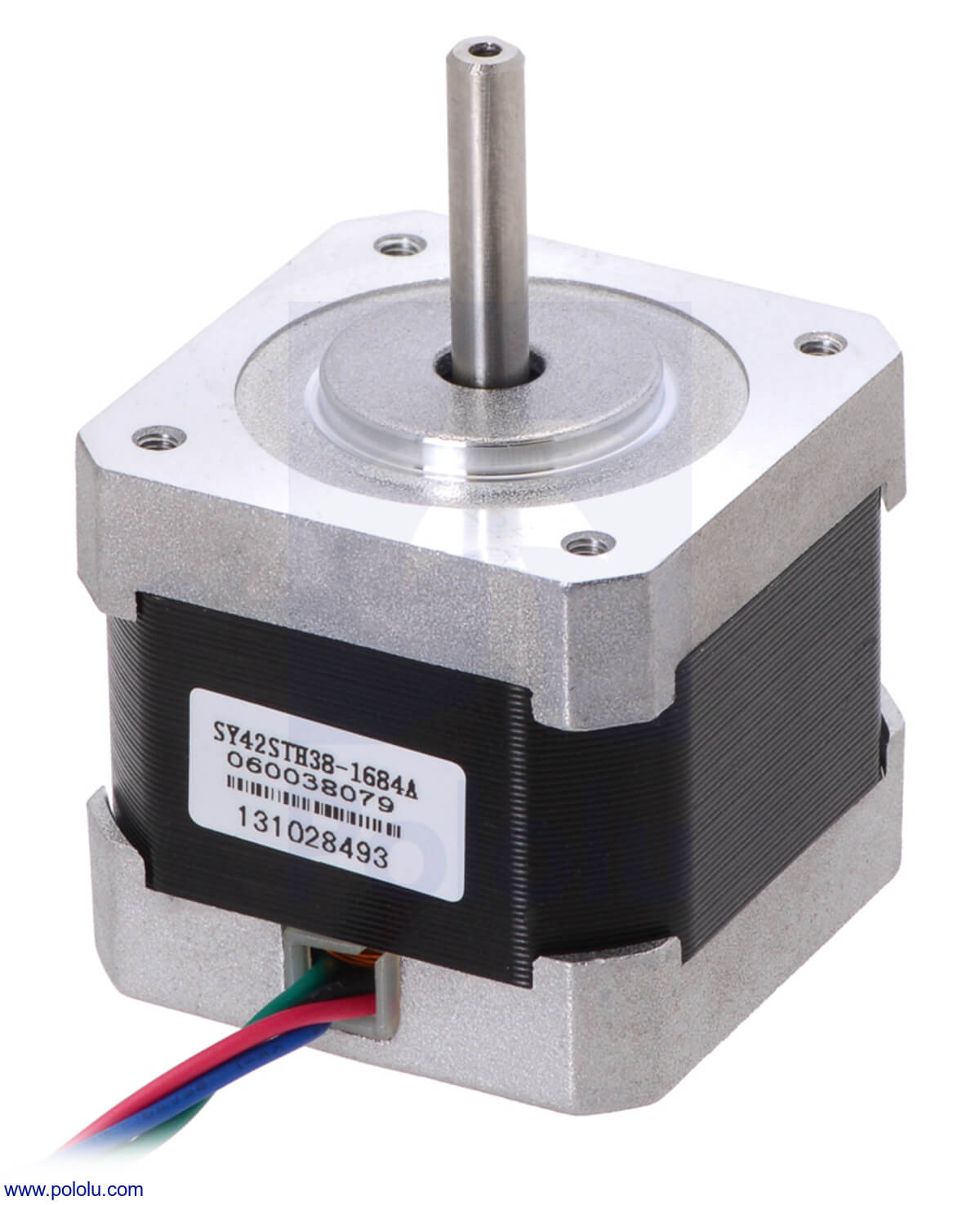
- Stepper motors are great because they do not require an additional sensor for position control: position can be precisely controlled by sending an open loop command. In addition, a gearbox is unnecessary to achieve high torque, which minimizes backlash.
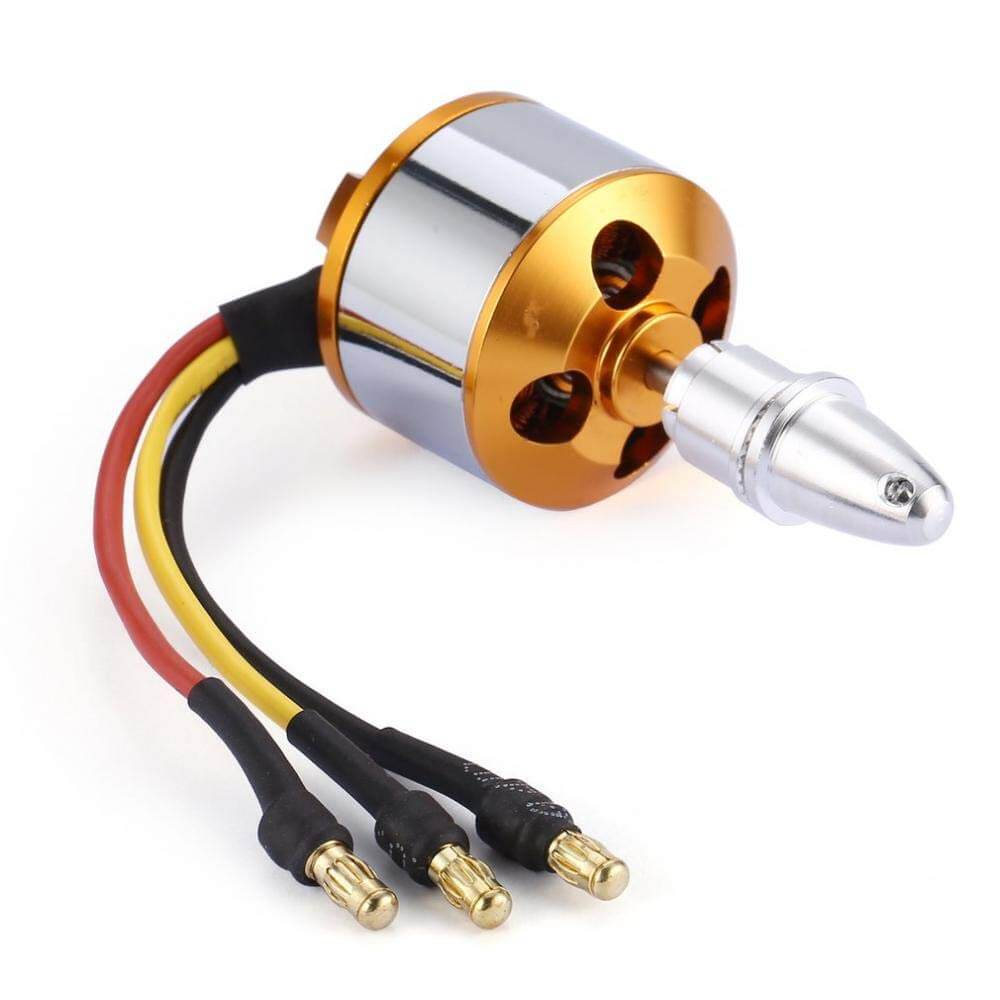
- BLDC Motors are more complex than DC motors and require specialized hardware to drive them. However, they are pretty efficient, with no need for a gearbox.
A motor driver is necessary to drive the motors in all three cases. The microcontroller cannot generate enough current to deliver sufficient torque. Instead, the microcontroller controls the motors indirectly, where the drivers function as a bridge of two sides.
Self-balancing Robot: IMU Sensor for the angle measurement
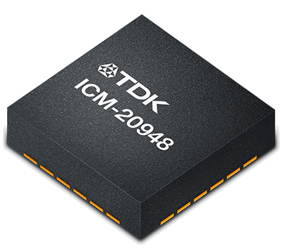
Another essential part of the self-balancing robot is an IMU sensor, whose primary purpose is to measure the tilt angle. Usually, the IMU sensor contains a gyroscope along with an accelerometer.
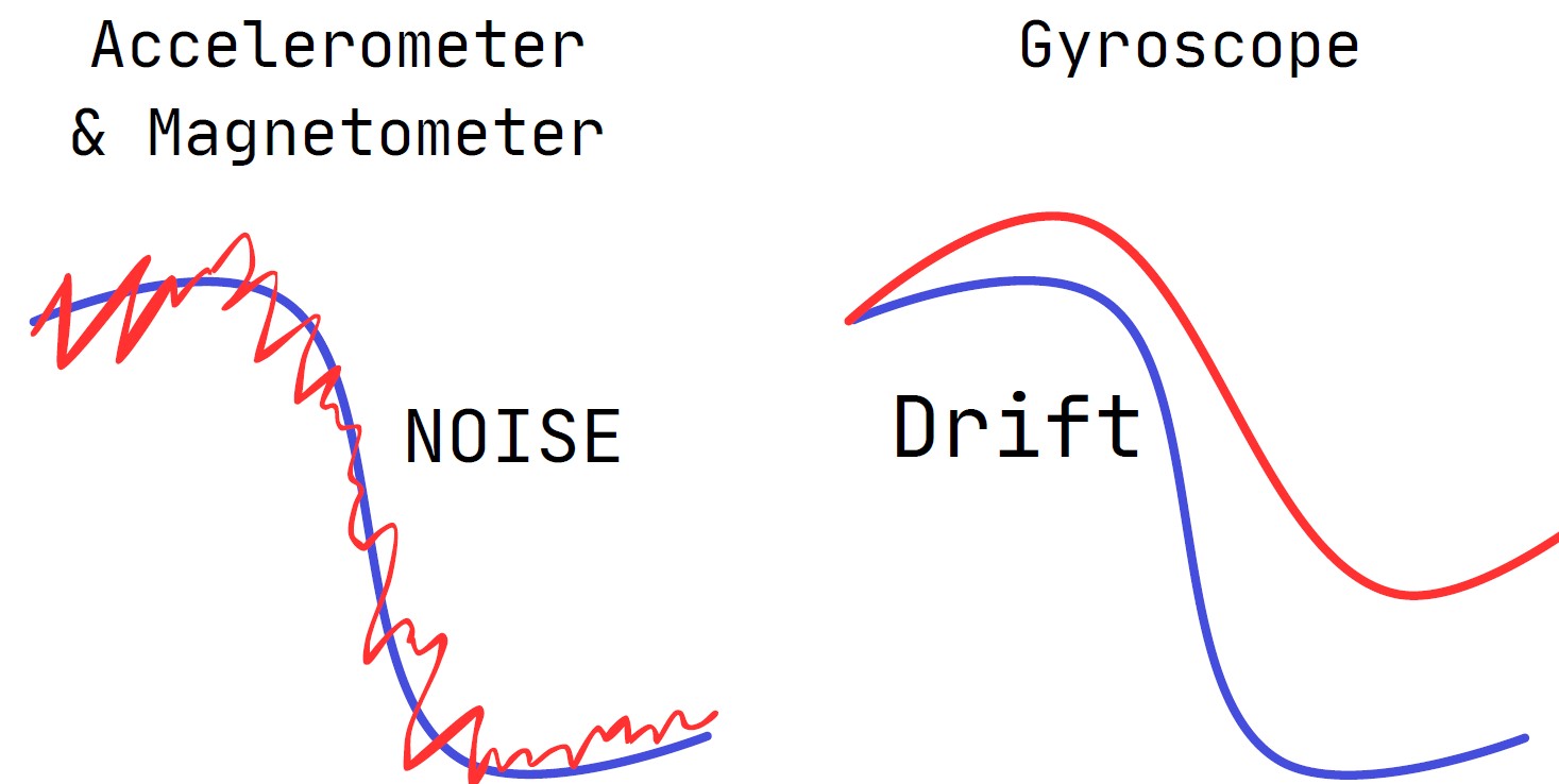
Theoretically, accelerometer measurements are sufficient to determine the tilt angle, but they suffer from high-frequency noise. Meanwhile, the gyroscope can estimate a precise tilt angle but is prone to drift. Therefore, it is vital to use data fusion algorithms to use the best from both parties for precise angle estimation. The algorithm for the data fusion could be a simple complementary filter or more advanced, based on the Kalman Filter.
Some Useful Links:
Self-Balancing Robot: Rotary encoder for position estimation
When using the DC or BLDC motor, you must use an encoder to estimate the position. Plenty of falsy materials on the web do not mention it at all. The fact is that the robot will keep drifting without the position feedback.
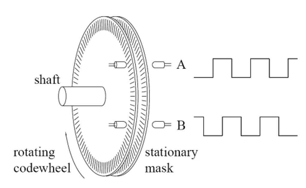
The operating principle of the rotary is pretty straightforward: it consists of a disk with evenly spaced teeth. Optical or magnetic transceivers generate a square-shaped signal whose number of edges varies with the disk's rotation speed. In STM32 MCUs, the Timer Peripheral already has a feature that interfaces with the encoders, automatically counting the signal edges.
Self-Balancing Robot: Control and Modeling
Once you have all the components for the robot and have managed the motor control and tilt angle estimation, the next step is to apply a control algorithm to keep the robot upright. The most common approach is to use a PID Controller. When your robot tilts to one side, the idea is to accelerate your robot to that direction to minimize the tilt angle. In addition, we also need to consider the position drift by having another PID controller for that purpose.
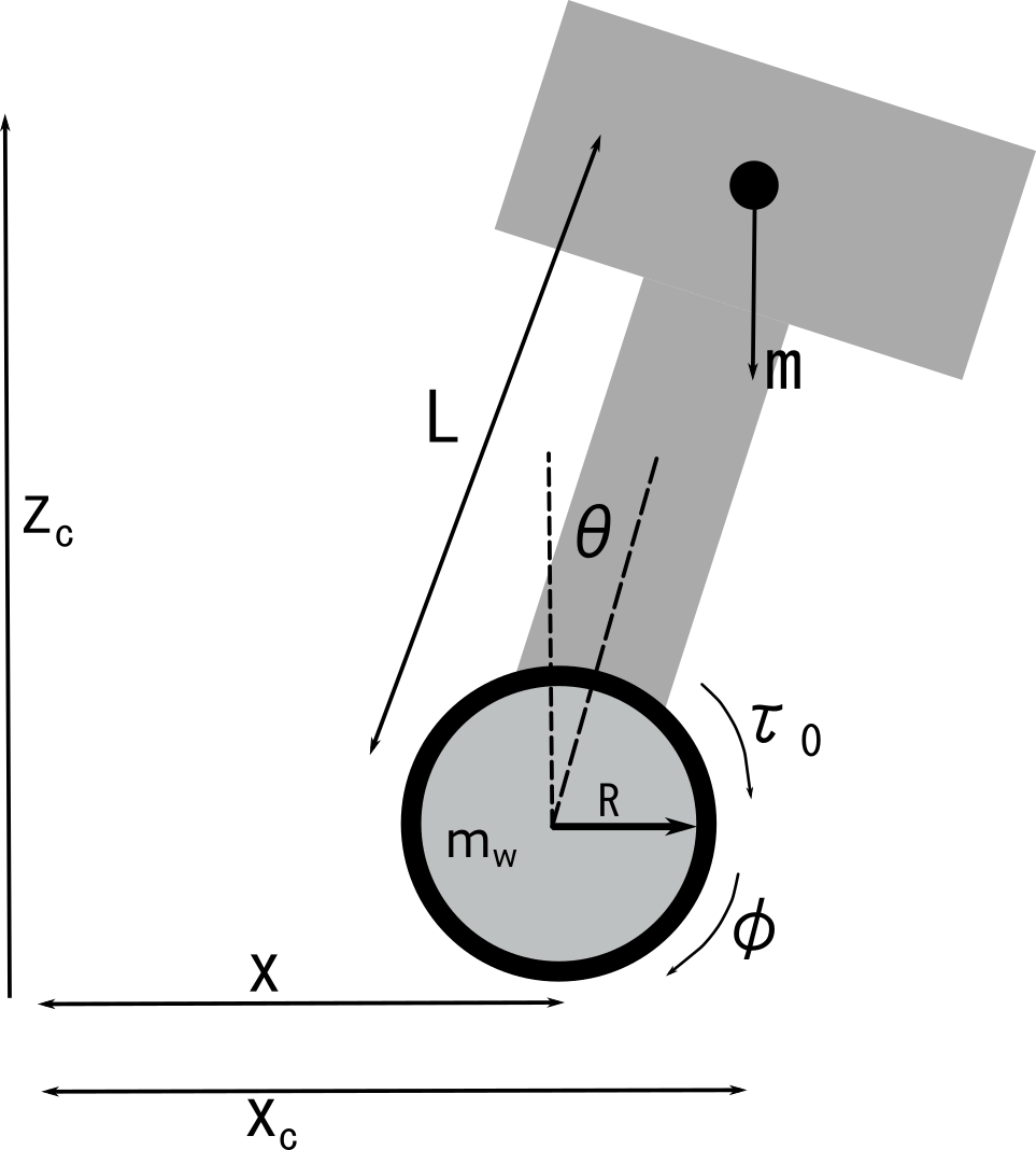
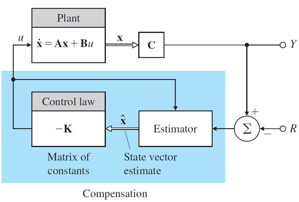
Another common approach is utilizing a state-space design to consider all output variables simultaneously. In this regard, using a Linear Quadratic Regulator (LQR) could be the easiest solution. However, this approach requires knowing the state-space design: control system technique for modeling and designing feedback control for linear systems.
As shown in the illustration below, it is essential to model the system using the motion equations and obtain the state-space representation of the robot. Then, a few lines of code in Matlab will allow you to obtain LQR gains. Next, you just need to implement the feedback using the gains you obtained.
Some Useful Links:
Complete Guide on Building the Balancing Robot
If you are looking for a comprehensive guide to building a balancing robot, please refer to my course, which covers all aspects of the design: hardware, control, and embedded programming. Specifically, I cover the following topics:
- DC Motor Control
- STM32 Timer Encoder
- PID implementation in C
- Embedded Programming in the STM32 MCU
- Control Theory: Linear Quadratic Regulator
- Working with RC Joysticks
Check the link below:
Building a Self-Balancing Robot: A Complete Guide