STM32 MPU6050 interface using I2C
Oct 13, 2025
This article explains how to communicate with a widely used Internal Measurement Unit (IMU) sensor, MPU6050, using an STM32 MCU. We will use STM32CubeMx along with the STM32 HAL API to program the microcontroller and set up the STM32 MPU6050 communication. I use the Nucleo-L476RG board, but the article can also be adapted to other STM32 boards. I also expect that you have already created a project and are familiar with the basic principles of programming STM32 MCUs.
Please find the MPU6050 datasheet and register map at the following links: link and link.
To sum up, this article helps you to
- Configure I2C peripheral in STM32 Using STM32CubeMx tool
- Reading/writing MPU6050 register via I2C using HAL API
- Configure MPU6050 registers
- Read accelerometer and gyroscope data from MPU6050
STM32 I2C Configuration using STM32CubeMx
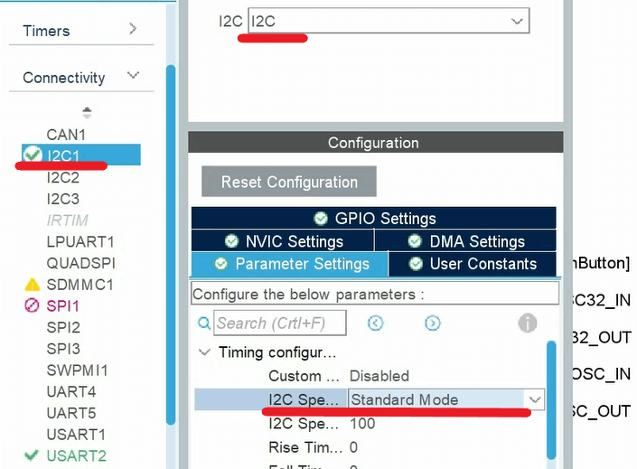
First, we configure the I2C interface using STM32CubeMX. Among categories, press Connectivity, then I2Cx. We enable I2C by choosing I2C mode, as shown in the Figure below. Then we select I2S Standard speed in Parameter Settings.
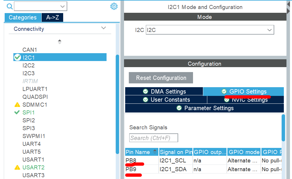
Within the GPIO settings, you will find the I2C SDA and CLK pins. In my case, I have PB8 and PB9. Do not forget to wire these lines to the corresponding MPU6050 pins.
Finally, we can save the file and generate code. At this point, I expect you have correctly wired the MPU6050 to the microcontroller. Basically, it is necessary to connect the I2C SDA and CLK lines. Also, do not forget to power the sensor.
STM32 MPU6050 Configuration
Before initiating communication, we can verify that the sensor is wired correctly using the HAL_I2C_IsDeviceReady function. This function has four arguments:
1. hi2c: pointer to the structure that contains the configuration information for the specified I2C. Check the configuration function of I2C.
2. devAddress:16-bit unsigned Device Address. In our case, we need to specify the MPU6050 address.
3. trials: Number of trials
4. Timeout: timeout.
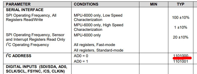
This function attempts to communicate with a device at the specified address for the Specified Timeout period; if successful, it returns HAL_OK. We also refer to the MPU-6050 datasheet to identify the device's address. On page 15 of the datasheet, the default sensor address is 1101000. There is an additional pin on the sensor that allows you to change the last bit of the address. But I expect that this pin is not set.
Finally, we have everything to write code. Also, when using the sensor's address, we add ’0’ at the end. I used the left shift operator to do that. Regarding the other parameters, the number of trials is 1, and the timeout is 100 ms.
HAL_StatusTypeDef ret = HAL_I2C_IsDeviceReady(&hi2c1, (1101000) << 1 + 0, 1, 100); if(ret == HAL_OK) {printf(”The device is ready”);} else {printf(”The device is not ready. Check cables”);}
Note that I used printf to check the function's output. If you are willing to use printf, you can refer to another article where I explain how to set up SWV to implement the printf function. Otherwise, you can use LEDs or other means to check the result.
STM32: printf over SWV
If the function returns HAL_OK, we can proceed and start communicating with the IMU sensor. Before diving into coding, let me explain a general working principle of digital sensors. Usually, the sensor comprises multiple registers with specific addresses. A register is a piece of memory that contains some data. Some registers affect the sensor's working condition, so we can control how the sensor operates by writing to them. Other registers store sensor measurements, so we can read them to obtain the actual data. And before reading the measurements, we need to write to specific registers to configure the sensor. One such register is Gyroscope Configuration register 27. The register description is on page 14 of the register map document.
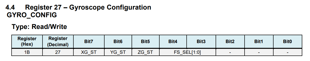
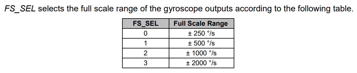
On this register, we have FS_SEL bits (bits 3 and 4) to change the full-scale range of the gyroscope readings. For instance, if we set these bits to zero, the full-scale range will be 250°/second. So if we read the gyroscope readings next time and get a maximum possible value, we can be sure that a 250° rotation happened.
Next, let me show you how to write to the register over I2C. For that purpose, we use the HAL_I2C_Mem_Write function. It has seven arguments:
- hi2c: pointer to the structure that contains the configuration information for the specified I2C. Check the configuration function of I2C.
- devAddress:16-bit unsigned Device Address. In our case, the address of MPU6050
- The address of the register to which we want to write. In our case, its value is 27.
- The size of the register in bytes. In our case, this argument equals 1.
- A pointer to the variable to be sent.
- The size of the variable to be sent. In our case, its value is 1.
- Timeout
We will set a 500 °/s full-scale range. To achieve this scale, we need to write the 00001000 value to register 27 (FS_SEL bits are ’01’ and the rest of the bits are zero). We define a one-byte variable and assign this value. Using all these pieces of information, we write the following code:
uint8_t temp_data = 0b000001000;
ret = HAL_I2C_Mem_Write(&hi2c1, (1101000) << 1+0, 27, 1,&temp_data, 1, 100);
if(ret == HAL_OK)
{printf(”Configuring gyroscope”);}
else
{printf(”Failed to configure gyroscope ”);}
Again, we use an if statement to verify that register 27 was successfully updated. Similarly, we can configure the accelerometer in Register 28. The primary interest is again in configuring the full-scale range of the accelerometer:
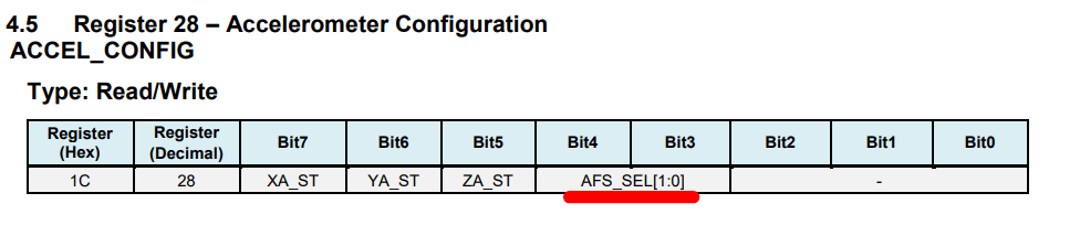
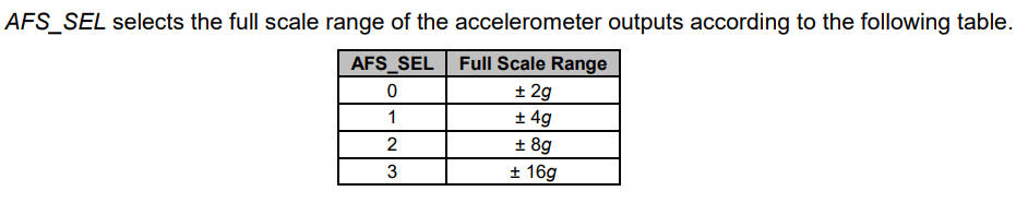
I set a 4g full-scale accelerometer range:
uint8_t temp_data = 0b000001000;
ret = HAL_I2C_Mem_Write(&hi2c1, (1101000) << 1+0, 28, 1,&temp_data, 1, 100);
if(ret == HAL_OK)
{printf(”Configuring accelerometer”);}
else
{printf(”Failed to configure acceleromter ”);}
There is one more step before measuring the accelerometer and gyroscope readings. By default, the sensor is in sleep mode. To wake up, we reset the Sleep bit in Register 107 (Power Management 1).
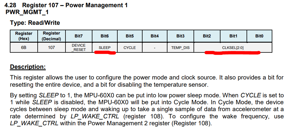
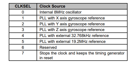
There is another parameter we need to configure using this register - the clock source of the sensor. We will set the internal clock as the clock source using the CLKSEL bits (we will set these bits to zero).
In other words, we reset all bits of the register to exit sleep mode and configure the clock sourse:
temp_data = 0;
ret = HAL_I2C_Mem_Write(&hi2c1, (1101000) << 1+0, 107, 1,&temp_data, 1, 100);
if(ret == HAL_OK)
{printf(”Exiting from sleep mode”);}
else
{printf(”Failed to exit from sleep mode ”);}
Reading accelerometer and gyroscope readings, STM32 MPU6050.
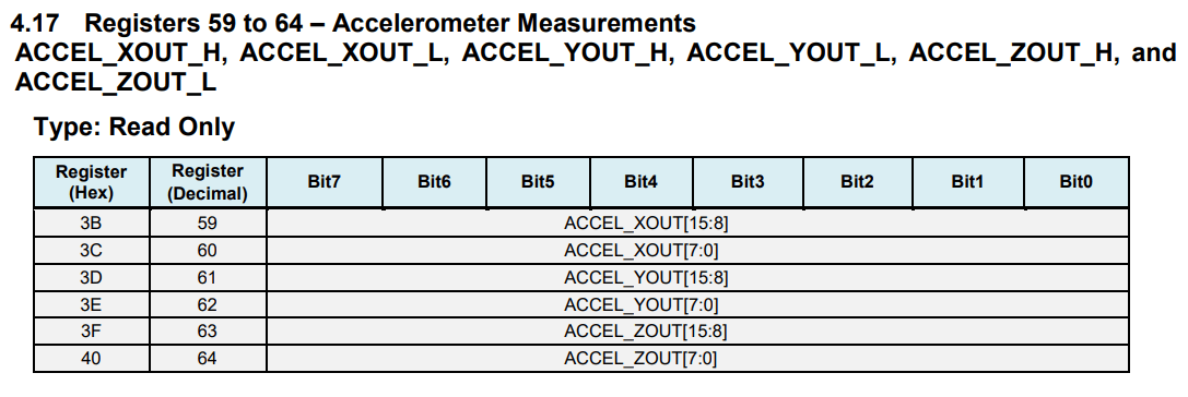
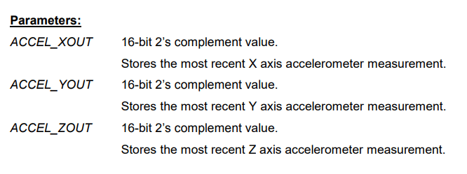
Starting at register 59, the MPU6050 registers contain Accelerometer, Temperature, and Gyroscope readings. We need to read 14 registers, starting from register 59, to extract all measurements. Let's discuss accelerometer measurements to understand the data format (registers 59-64). As the figure shows, we have three axes, and each axis reading is a 16-bit 2’s-complement number. In other words, every measurement consists of two bytes. For instance, register 59 comprises the lower bit, whereas register 60 contains the upper byte of the x-axis accelerometer measurement.
Similarly, we have the y-axis and the z-axis. This implies that we need to read two consecutive bytes to obtain the correct measurement values after reading those registers. This rule applies to readings from other sensors.
I2C protocol supports serial read operation. Serial read allows readings of multiple consecutive registers in a single transaction. This is already implemented in STM32 HAL libraries using the HAL_I2C_Mem_Read function. This function has seven arguments:
1. hi2c: pointer to the structure that contains the configuration information for the specified I2C. Check the configuration function of I2C.
2. devAddress:16-bit unsigned Device Address. In our case, the address of MPU6050 address.
3. The address of the onset register we want to read. In our case, its value is 59.
4. The size of the register in bytes. In our case, this argument equals 1.
5. A pointer to the buffer to store data.
6. The number of registers(bytes) to be read. In our case, its value is 14.
7. Timeout
Finally, we write this code to retrieve measurements from MPU6050:
int16_t x_acc;
uint8_t data[14];
HAL_I2C_Mem_Read(&hi2c1, (1101000 << 1) + 1, 59, 1, data, 14, 100);
x_acc = ((int16_t)data[0] << 8) + data[1];
Although we read all sensors’ readings, I only showed how to encapsulate the first two bytes to extract the x-axis measurement. Similarly, we can retrieve the y-axis (elements 2 and 3), z-axis (4 and 5), and other sensor readings.
Here is a video that provides more detailed information about STM32 MPU6050 communication: