
STM32 Bootlader P2: Linker Script, Vector Table, and Jumping to the Application
Jan 14, 2026
In the first part of the tutorial, we laid the groundwork for developing our bootloader. At this point, we have a fully functional UART interface and a Python script for sending/receiving serial data. In addition, the project includes a library to store the data within flash memory. If you miss the first part, check out the link below
https://www.steppeschool.com/blog/stm32-bootloader-part1-flash-uart
Also, the source code is available on within the course:
https://www.steppeschool.com/stm32-bootloader-course
In the second part, we finalize and address all gaps in the bootloader design project.
STM32 Bootloader: Flash memory organization
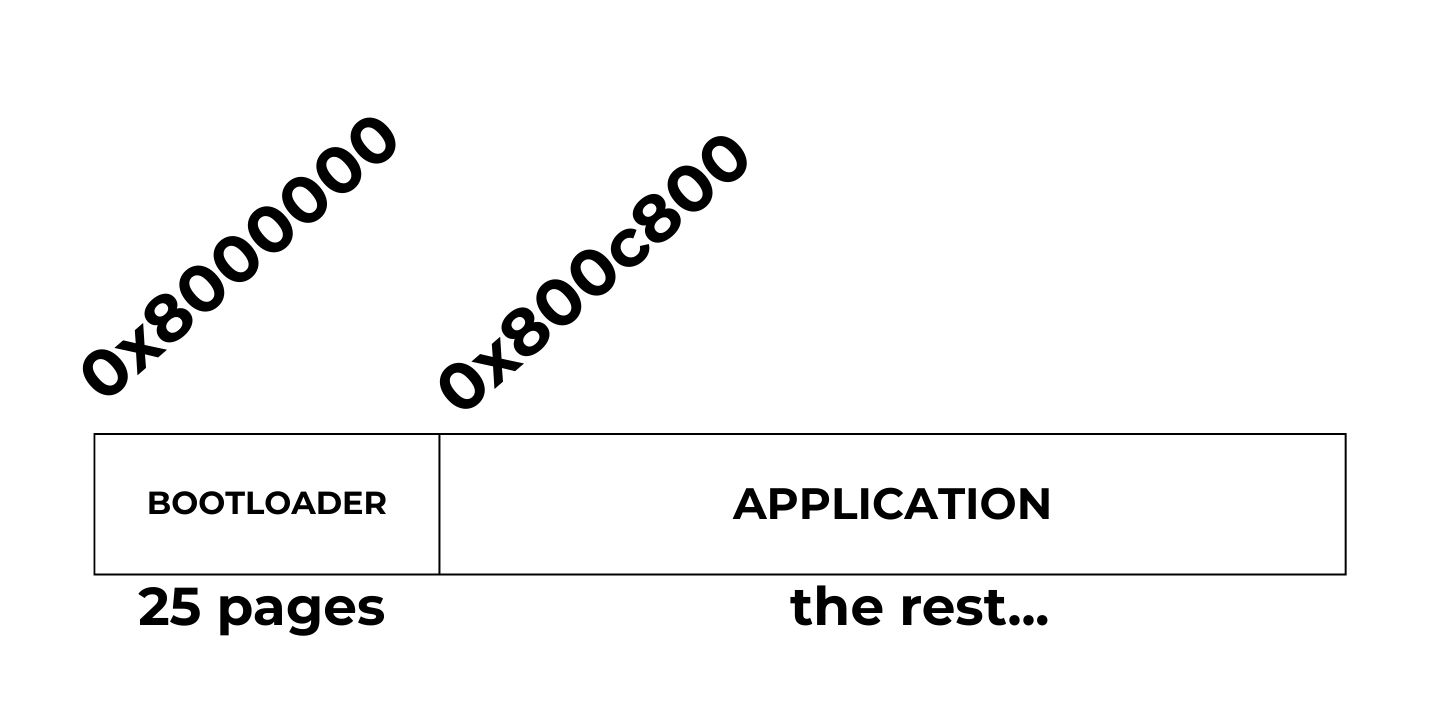
The figure below illustrates how we arrange the bootloader and application within a flash memory. In this tutorial, I will devote 25 pages of the flash memory to the bootloader and the rest to the application. Since each page is 2K (2048 bytes on STM32L4 MCUs) and the flash memory start address is always 0x80000000, the application start address will be 0x8000000 + 2048 * 25 = 0x800c800. We will need this number when configuring the application project.
Note that the page size on your microcontroller may differ. Refer to the reference manual to obtain this information.
STM32 Bootloader Design Complete Course
If you want a deeper, step-by-step walkthrough, I also cover this topic in my Custom STM32 Bootloader Design course, where we build a bootloader from scratch and explain the linker script, vector table relocation, and application jump in detail.
https://www.steppeschool.com/stm32-bootloader-course
STM32 Bootloader: Updating the Linker Script and redefining VTOR
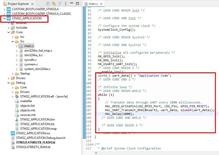
In this part of the tutorial, we create an application project. We will build the binary of the project, so we can send it to the bootloader using the Python script
There is nothing special about this project. For testing, I will send an "Application code" message via the UART Interface every second.
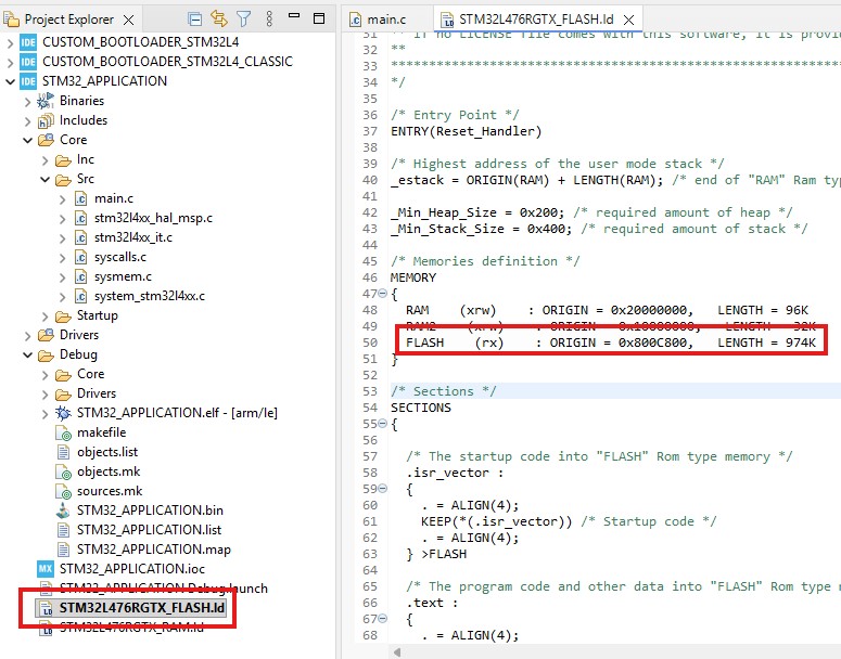
As we discussed earlier, we denote the first 25 pages to the bootloader, while the rest to the application file. When building the project, we must specify the project memory start address as 0x800C800 (0x8000000 + 0x800 x 25 = 0x800C800). Open the linker script file, and enter the start address in a flash field. Also do not forget to change the Length field
VTOR (Vector Table Offset Register) is a register within the ARM Cortex-M core that specifies the memory address of the interrupt vector table.
Normally, in a simple project without a bootloader:
-
The vector table is placed at address 0x08000000 (start of Flash)
-
On reset, the CPU:
-
Reads the initial stack pointer from the address
0x08000000 -
Reads the Reset_Handler address from
0x08000004
-
-
All interrupts (SysTick, EXTI, timers, etc.) use this same table
In this case, VTOR is either left at its default value or explicitly set to 0x08000000
When we design a bootloader, Flash memory is split into two regions:
- 0x8000000 - Bootloader
- 0x800c800 - Application
This means the VTOR value must be updated in the application project as the application memory onset.
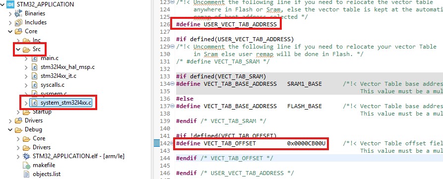
We open system_stm32l4xx.c (the file name varies by MCU used) and uncomment the USER_VECT_TAB_ADDRESS. Then we define the offset according to the application onset memory address.
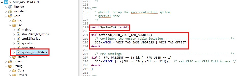
These changes are enough to set the right VTOR value. During System Initialization, the MCU updates the VTOR register, as shown in the screenshot below.
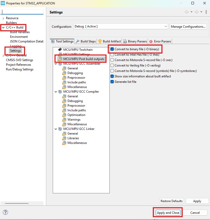
Next, we need to generate the binary file during the build. Open project settings (press the right button of the mouse on the project name). Then C/C++ Build, Settings, and Post-build outputs. Tick the box as shown in the screenshot below. Finally, press "Apply and Close ."
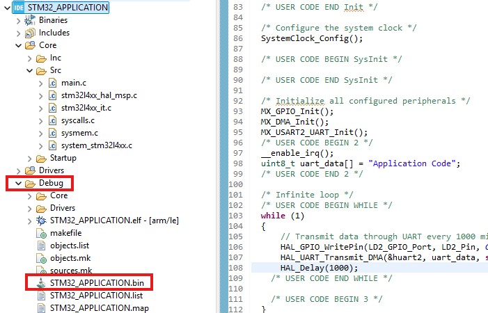
If everything is done correctly, we will see the .bin file in the Debug folder. This means that our application binary file is ready.
STM32 Bootloader: Data Packet Format and Sending the Binary File
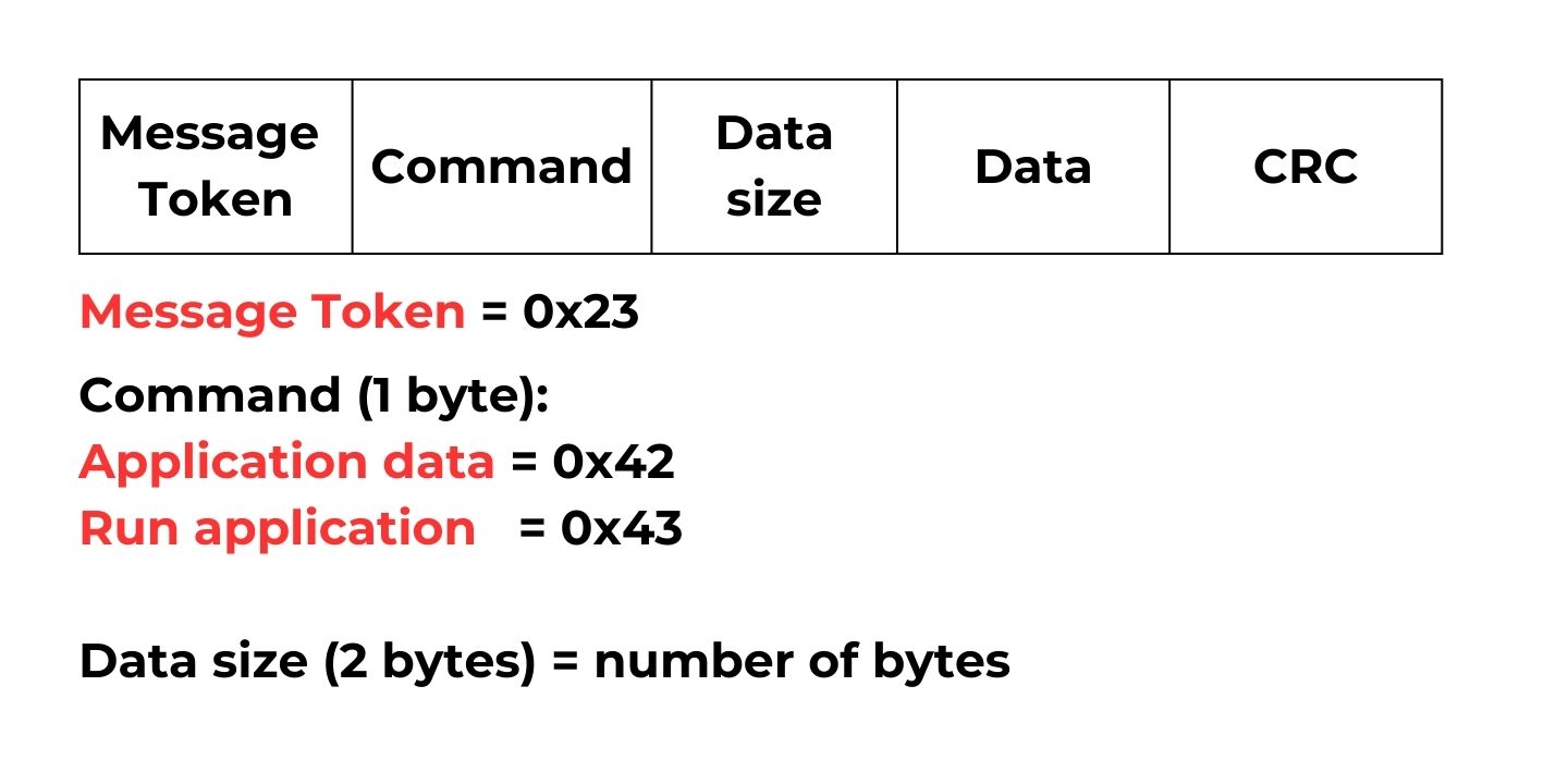
Our next step is to transmit this file over the UART and request that the microcontroller store it in the flash memory. Then, if the MCU runs the application, it will execute the logic defined in the application project. To handle the complexities of data transactions and ensure reliable data transfer, I created a simple protocol for data packets. The figure below shows the packet format. The first byte of the packet is always a message token with value 0x23. Then, the command byte follows. Currently, there are three commands:
- Application Data = 0x42: We send this command when transmitting a chunk of the binary file
- Run application = 0x43: This command is necessary to run the application once the binary file transfer is over
Later, we can add more commands, such as firmware version requests, protections, and application erasure.
I created macros and a struct to define the command types and easily handle the data transactions
#define BOOT_RUN_APPLICATION 0x43 /*!< Run application, */
#define BOOT_UPDATE_REQUEST 0x42 /*!< BOOT UPDATE request, */
#define MESSAGE_TOKEN 0x23 /*!< # symbol to define the message onset*/
#define BOOT_NACK 0xaa
#define BOOT_ACK 0x5f
typedef enum
{
SERIAL_OK = 0x00,
SERIAL_MESSAGE_ERROR = 0x01,
SERIAL_SIZE_ERROR = 0x02,
SERIAL_CRC_ERROR = 0x03
} Serial_StatusTypeDef;
typedef struct
{
uint8_t rw_request;
uint8_t *data;
uint16_t data_size;
uint32_t crc_value;
}__attribute__((__packed__)) CommandTypeDef;
And the function parse_request parses the data packet and returns the error code in case of faulty data transactions:
uint8_t parse_request(CommandTypeDef* command, uint8_t *data, uint16_t size){ if((uint8_t)(*data) == MESSAGE_TOKEN) { if( (uint8_t)(*(data + 1)) == (BOOT_UPDATE_REQUEST) || (uint8_t)(*(data + 1)) == (BOOT_RUN_APPLICATION)) { command->rw_request = *(data + 1); command->data_size = *((uint16_t *)&data[2]); // data + 2 (message token and command code) + 2 (data size) + 4 (crc) if (size != command->data_size + 2 + 2 + 4) { return SERIAL_SIZE_ERROR; } command->data = &data[4]; command->crc_value = *((uint32_t *)&data[4 + command->data_size]); if(boot_verify_crc(data, size - 4, command->crc_value)) { return SERIAL_CRC_ERROR; } } else { // Wrong data format return SERIAL_MESSAGE_ERROR; } } else { return SERIAL_MESSAGE_ERROR; } return SERIAL_OK;}
STM32 Bootloader: Python function for sending the binary file
In the Python script, I defined a function to send the binary file. Of course, it is impossible to send the whole file as a single packet. Instead, we divide it into small chunks (WINDOW_SIZE).
def update_flash_mem(serial_com, file_name): WINDOW_SIZE = 128 try: flash_bin_file = open(file_name, 'rb') except: Exception('cannot open the bin file') size = os.path.getsize(file_name) # data token and command data_token = [MESSAGE_TOKEN, BOOT_UPDATE_REQUEST] data_token_bytes = bytes() data_token_bytes = data_token_bytes.join((struct.pack('<'+format, val) for format,val in zip('BB',data_token))) size_copy = size while size > 0: # actual data data_sent = flash_bin_file.read(WINDOW_SIZE) size = size - len(data_sent) data_sent = data_token_bytes + struct.pack('<H',len(data_sent)) + data_sent send_data_serial(serial_com, data_sent) print('Firmware update ' + str(int(100 * (size_copy - size)/size_copy)) +' %' +': ' + int(50 * (size_copy - size)/size_copy) * '#', end = '\r') if read_boot_reply(serial_com) != BOOT_ACK: print("flash update failed ") Exception("flash update failed") break if size == 0: print('Firmware update ' + str(int(100 * (size_copy - size)/size_copy)) +' %' +': ' + \ int(20 * (size_copy - size)/size_copy) * '#') print('Firmware update is over')STM32 Bootloader: Switching to the Application
After we handled the transmission of the binary file, the next crucial step is to manage the application's execution. After all, what is the point of designing the bootloader if we cannot run the application? Before switching to the application, we must follow several essential steps. First, we disable interrupts. If an interrupt is triggered just before switching the application, the MCU may crash once we change the Vector Table address, resulting in Hardfault. Then we deinitialize the peripherals, if needed, and redefine the Main Stack Pointer, which is stored at the start of the application data. The next four bytes in the application file store the address of the Reset handler, the first function to run. To sum up, the function below follows all these steps. We extract its address and run it after completing the preceding steps.
void bootloader_jump_to_user_data(void){ void (*app_reset_handler)(void);
//setting main stack pointer // first 4 bytes hold the address of the stack pointer uint32_t msp_value = *(volatile uint32_t*)(APPPLICATION_PROGRAM_ADDRESS); /* Disable all interrupts */ __disable_irq();
/* De-init peripherals if needed */ HAL_RCC_DeInit(); HAL_DeInit();
__set_MSP(msp_value);
// next four bytes hold the address of the reset handler function uint32_t app_reset_handler_address = *(volatile uint32_t*)(APPPLICATION_PROGRAM_ADDRESS + 4); app_reset_handler = (void*)app_reset_handler_address; //run the reset handler of the application app_reset_handler();
}