STM32 Bootloader Design Part 1: UART, CRC, and Python script
Dec 12, 2025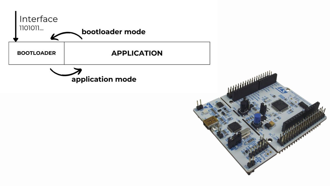
Whether you are a professional or a hobbyist in STM32 programming, knowing how to design custom bootloaders will allow you to do many incredible things. In product development, a custom bootloader is a must-have feature.
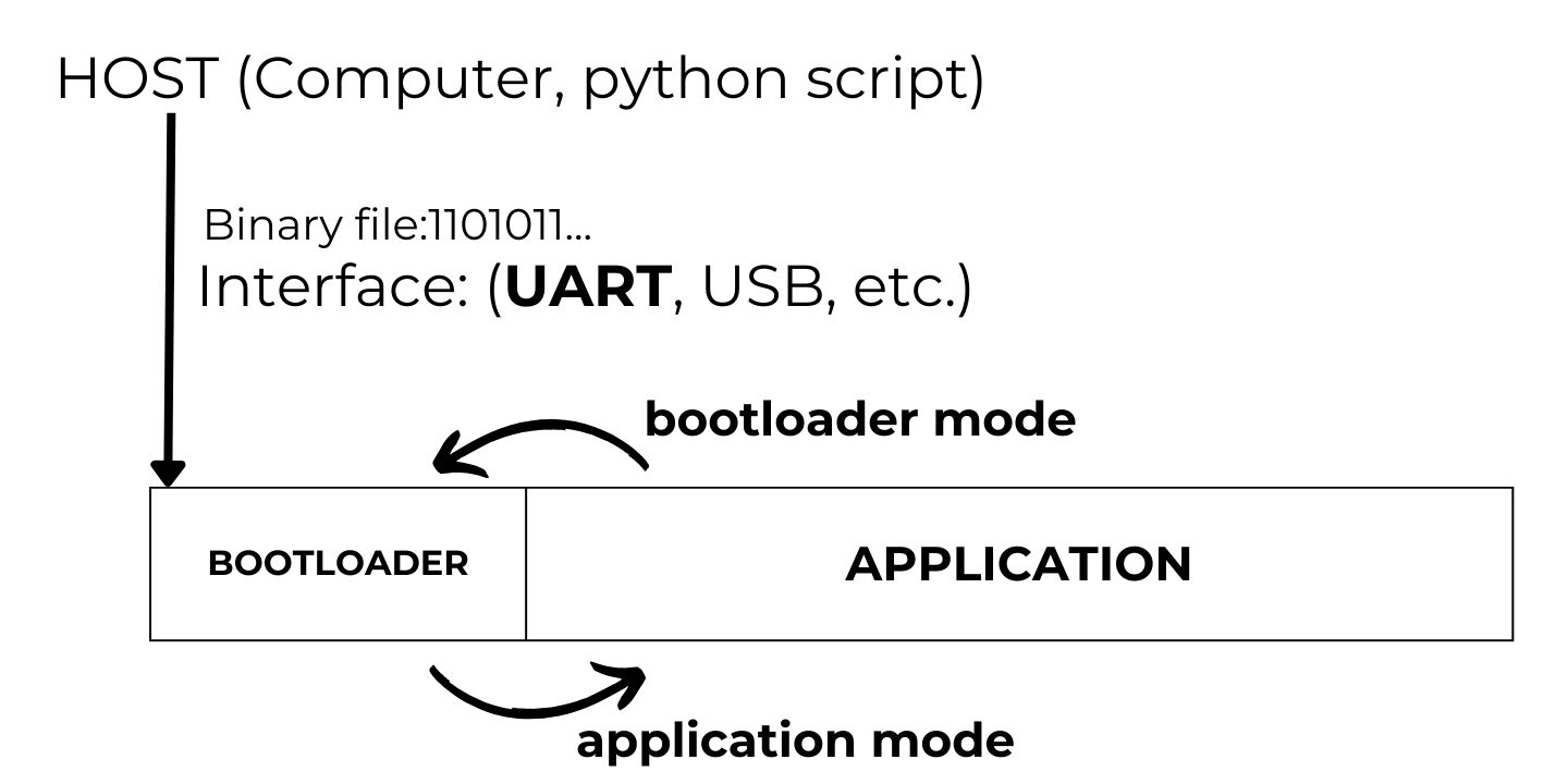
Imagine you have designed a smartwatch and delivered it to customers. The next big question is how to update the device firmware when adding new features or fixing bugs. The solution is to provide a device feature that allows the application to be updated wirelessly. The smartphone application sends the binary file to the device. It updates the flash memory and installs a new firmware version. In other words, the application should always have the ability to update itself by receiving a binary file through an interface (wireless, USB, UART, etc.).

In this series of articles, I aim to provide a comprehensive guide to designing bootloaders for STM32 MCUs. We will cover all essential topics and follow rigorous steps to avoid getting lost in this complex topic. Hopefully, you will be confident in designing bootloaders and mention it in your CV. So let's get started! Topics to be covered:
- What is a bootloader?
- UART DMA communication
- Cyclic Redundancy Check (CRC)
- Python program to send/receive serial data
- Flash memory
- Bootloader Design
The final note is that I will use the Nucleo-L476 board in this tutorial, but you can apply the guidelines to any other STM32 MCUs.
STM32 Bootloader Design Complete Course
If you want a deeper, step-by-step walkthrough, I also cover this topic in my Custom STM32 Bootloader Design course, where we build a bootloader from scratch and explain the linker script, vector table relocation, and application jump in detail.
https://www.steppeschool.com/stm32-bootloader-course
Also, the source code is available on within the course:
https://www.steppeschool.com/stm32-bootloader-course
Second Part of the article:
https://www.steppeschool.com/blog/stm32-bootloader-p2-vtor-linker-booting
STM32 Bootloader and Flash Memory
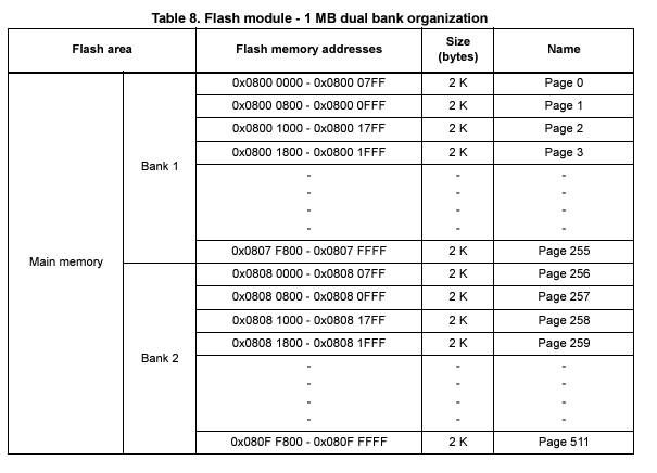
Flash memory is a long-lasting, non-volatile storage chip widely used in embedded systems. It is mainly used to store the application code. When we compile our project and flash the MCU, ST-Link updates the flash memory from the compiled binary. The figure below illustrates the structure of flash memory. It is usually divided into equal-sized pages and has a defined address. Once you write data in this region, that data will be stored even if you power off the microcontroller. Therefore, we refer to the memory unit as non-volatile.
A bootloader is software that loads the main program or updates it. Vendors typically provide a bootloader with a device, and STM32 MCUs are no exception. Even if we can modify some vendor bootloader configurations, we cannot fully replace the vendor bootloader.
When designing a bootloader, we allocate a small portion of flash memory to the bootloader code. The rest will be devoted to the application code. When triggering the application - setting a particular GPIO pin or sending a UART command - the MCU will jump to the bootloader. Then it updates the application code by receiving binary data over an interface (e.g., UART, Bluetooth). Once the application code renews, the MCU can return to the application. The image below illustrates how it works.
STM32 UART Communication and STM32 CRC
In this tutorial, we will send the application code to the microcontroller via the UART Interface. So, our first task is to configure this peripheral on the STM32 MCU. I skip explaining how to create a new project, configure the clock, and other basic steps. If you need a more rigorous guide on these topics, I would recommend my STM32 Programming course for beginners:
STM32 Programming Course for Beginners
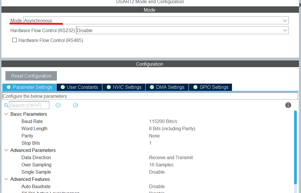
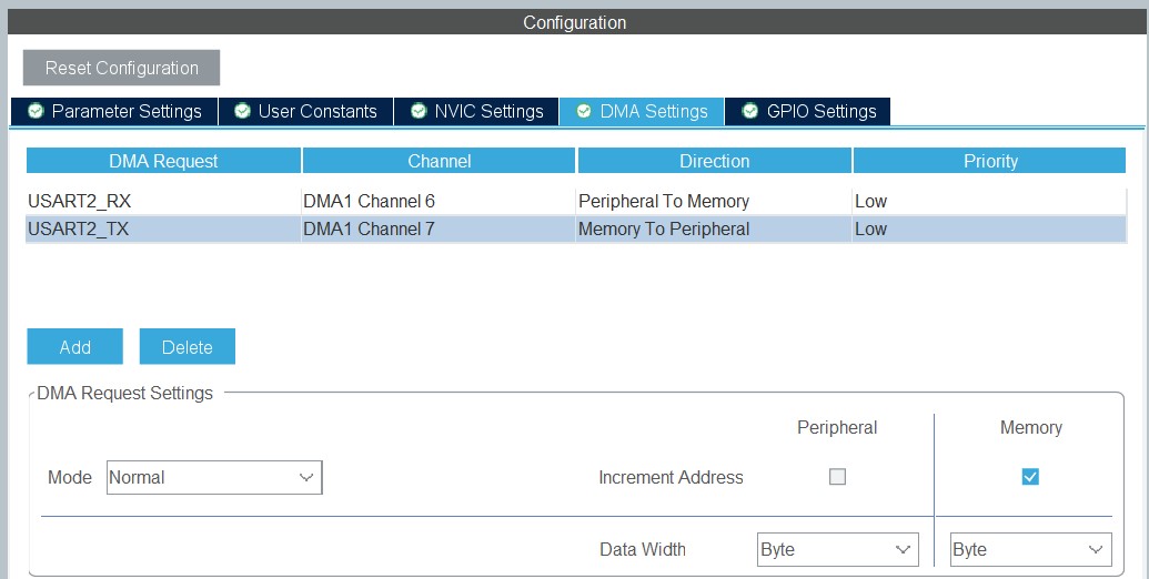
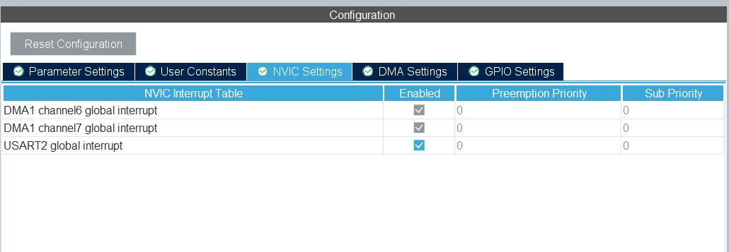
We enable it in asynchronous mode and keep the default baud rate and other configuration values. In addition, enabling DMA and interrupts are steps we need to take next. Check the screens below.
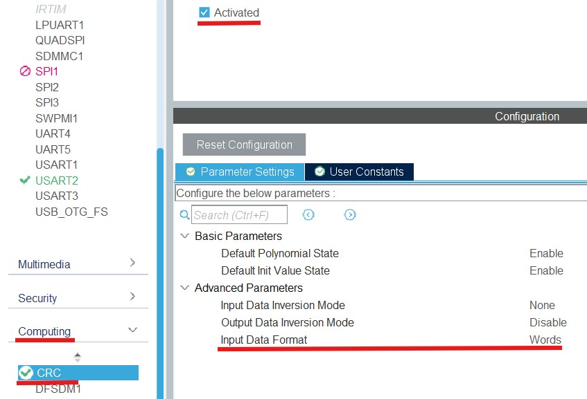
When transmitting the application binary file, we must be 100% certain that our data is not corrupted. Otherwise, as you might guess, our application will malfunction. That is why we will apply the Cyclic Redundancy Check (CRC) to detect accidental changes in digital data. In CRC, we calculate a checksum of the data and append it to the data. Upon retrieval, we can compute the check value and compare it with the received one. If they match, we can be confident in the received data. There is plenty of material online about CRC, so I will skip the details and jump straight to its implementation in STM32 MCUs. Under Computing, activate CRC and choose ’words’ as the input data format.
Finally, we save the file and generate the code.
Next, we define the following function, which computes the CRC of the received data and compares it with the received one.
uint8_t boot_verify_crc(uint8_t *data, uint8_t len, uint32_t crc_host){ uint32_t crc_value = 0xff; for(uint32_t i = 0; i < len; i++) { uint32_t i_data = data[i]; crc_value = HAL_CRC_Accumulate(&hcrc, &i_data, 1); } __HAL_CRC_DR_RESET(&hcrc); if (crc_value == crc_host) { return 0;
}
return 1;
}
STM32 UART Receive to Idle
To receive data via UART, we usually specify the data length. It is not very convenient because the data size may vary over time. This situation could cause issues, including data loss and incorrect data parsing. Happily, we can receive the entire packet of arbitrary size by leveraging the fact that the IDLE event occurs when the packet transaction completes. In STM32 MCUs, this feature has already been implemented in the HAL API. So, we can call the following function to receive data packets of varying sizes:
HAL_UARTEx_ReceiveToIdle_DMA(&huart2, received_data, sizeof(received_data));
In this function, the arguments are the UART handler, buffer pointer, and the maximum buffer size. I set the last argument to a relatively high value to ensure we receive the entire packet in a single row. The function above will trigger a callback when the data is received. We can call that function again within the callback to receive the next packet.
void HAL_UARTEx_RxEventCallback(UART_HandleTypeDef *huart, uint16_t Size){ uart_size = Size; HAL_UARTEx_ReceiveToIdle_DMA(&huart2, received_data, sizeof(received_data));}
Finally, we can add the following lines to the while loop to check the CRC on each data packet.
............while (1){ if(uart_size) { if(boot_verify_crc(received_data, uart_size - 4, *((uint32_t *)&received_data[uart_size - 4]))) { printf("crc is wrong \n"); } else { printf("CRCs match each other \n"); printf("message is %s \n", (char*)received_data); }
uart_size = 0; ... ... ...
}
Python Program to send data through UART
Once we have configured the UART and CRC, we can switch to the Python program to handle serial port communication and CRC computation.
We use the function below to compute CRC in Python:
def compute_crc(buff, length): crc = 0xFFFFFFFF #print(length) for byte in buff[0:length]: crc = crc ^ (byte) for i in range(32): if(crc & 0x80000000): crc = (crc << 1) ^ 0x04C11DB7 else: crc = (crc << 1) return crc & 0xFFFFFFFF
When we send data, we use this function to add the check value data:
def send_data_serial(serial_com, data): data = data + (struct.pack('<I',compute_crc(data, len(data)))) serial_com.write(data)
Finally, we can use PySerial (pip install pyserial) to send a message that includes the checksum. In the code snippet below, it is crucial to choose the right COMPORT name.
import struct import serial comport = "COM6" serial_com = serial.Serial(port = comport,baudrate = 115200, timeout = 15) message = "Ukulele ukulele \n" message = struct.pack('<B' % len(message), message) send_data_serial(serial_com, message)
STM32 FLASH Memory
So far, we configured the UART Interface and CRC to receive the application binary file. Our next step is to store this data in Flash memory so the STM32 MCU can execute it. The function below accepts an address to store the data, a data pointer, and a data length. We use the HAL_FLASH_PROGRAM function to write 8 bytes of data per iteration.
In addition, this memory unit is special in that you can reset bits but not set them. Hence, we utilize a special function to erase the necessary pages when all bits are set.
As I said earlier, both the bootloader and the application reside in flash memory. When erasing, we must be extremely careful not to erase the bootloader code. Hence, I explicitly partition the flash memory into two regions to avoid this issue: the first 25 pages for the bootloader, and the rest for application memory.
Considering the fact that the page size is 2048 bytes (this number might vary by the MCU type, check the reference manual), the onset address will be 0x800C800 = 0x8000000 + 2048 * 25
Finally, the code snippet below incorporates functions for erasing and storing data in the flash memory.
#define APPLICATION_ADDRESS 0x800C800UL
void erase_flash_memory()
{
FLASH_EraseInitTypeDef flash_erase_struct = {0};
uint32_t error_status = 0;
HAL_FLASH_Unlock();
// defining the members of a struct
flash_erase_struct.TypeErase = FLASH_TYPEERASE_PAGES;
// defining an onset number page to be erased
flash_erase_struct.Page = (APPLICATION_ADDRESS - FLASH_BASE) / FLASH_PAGE_SIZE;
// number of pages to remove
flash_erase_struct.NbPages = (FLASH_BANK1_END + 1UL - APPLICATION_ADDRESS)/ FLASH_PAGE_SIZE;
// First Bank 1
flash_erase_struct.Banks = FLASH_BANK_1;
// erase the pages, this step is mandatory
HAL_FLASHEx_Erase(&flash_erase_struct, &error_status);
// defining an onset number page to be erased
flash_erase_struct.Page = (FLASH_BANK1_END + 1UL)/ FLASH_PAGE_SIZE;
// number of pages to remove
flash_erase_struct.NbPages = (FLASH_BANK2_END - FLASH_BANK1_END)/ FLASH_PAGE_SIZE;
// First Bank 1
flash_erase_struct.Banks = FLASH_BANK_2;
// erase the pages, this step is mandatory
HAL_FLASHEx_Erase(&flash_erase_struct, &error_status);
}
void store_flash_memory(uint32_t memory_address, uint8_t *data, uint16_t data_length)
{
uint8_t data_temp[8];
HAL_FLASH_Unlock();
int pointer_element = 0;
// using while loop, convey all data to the flash memory
while (data_length > 8)
{
HAL_FLASH_Program(FLASH_TYPEPROGRAM_DOUBLEWORD, memory_address + pointer_element,
*((uint64_t *)&data[pointer_element]));
pointer_element += 8;
data_length -= 8;
}
if(data_length > 0)
{
for(int i = 0 ; i < data_length ; i ++)
{
data_temp[i] = data[pointer_element + i];
}
HAL_FLASH_Program(FLASH_TYPEPROGRAM_DOUBLEWORD, memory_address + pointer_element, *((uint64_t *)data_temp));
}
// lock the memory
HAL_FLASH_Lock();
}
Once we lay the solid groundwork, we can switch to the second part of the tutorial, where we dive into the linker script, vector table, and sending the binary file:
https://www.steppeschool.com/blog/stm32-bootloader-p2-vtor-linker-booting