STM32 CAN Bus Tutorial P3, Sending Data between nodes
Dec 04, 2025
So, let's continue our endeavor to grasp and implement the STM32 CAN BUS. If you miss the previous two parts of the tutorial, please refer to the following links:
The Source Code:
https://www.steppeschool.com/stm32-can-bus-course
In this section, we will finally send data between two nodes. For that purpose, we will use the same code we developed in the last part, splitting it into two projects: one for the RX and another for the TX. For that, we duplicate the existing project and rename the new projects (copy and paste). Also, do not forget to change the .ioc file name. Check the screenshot below.
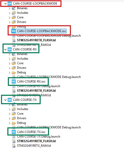
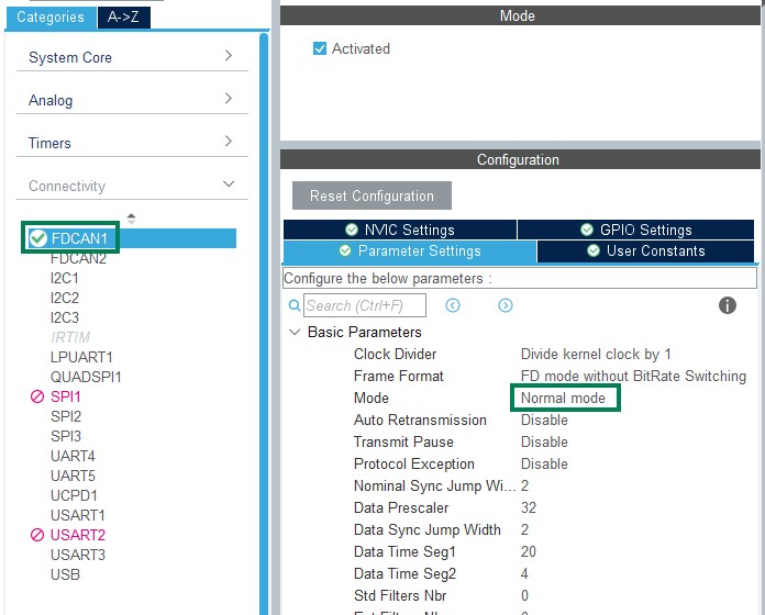
Within the RX project, we delete everything related to Tx, and in the TX project, we delete everything related to the RX. Finally, in both projects, we change the mode from loopback to a normal one.
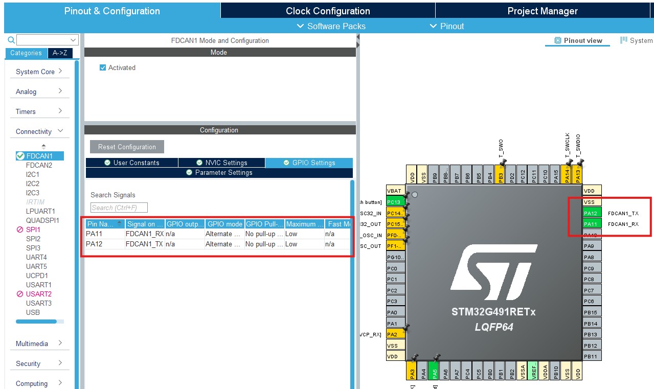
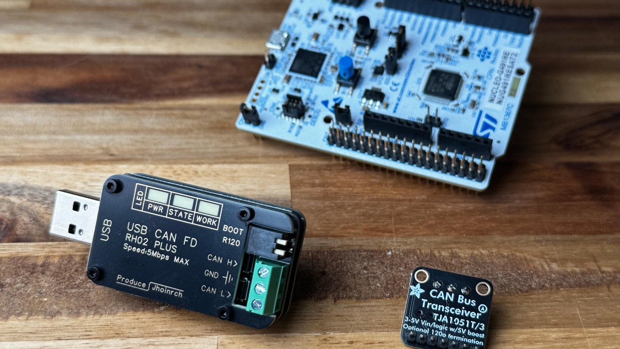
Once the projects are ready, we will create a setup consisting of two Nucleo-G491 MCUs connected to CAN Transceivers (I used TJA1051T ), which are wired together via CAN_H and CAN_L lines. To find the TX and RX pins of the CAN peripheral, refer to the project's .ioc file.
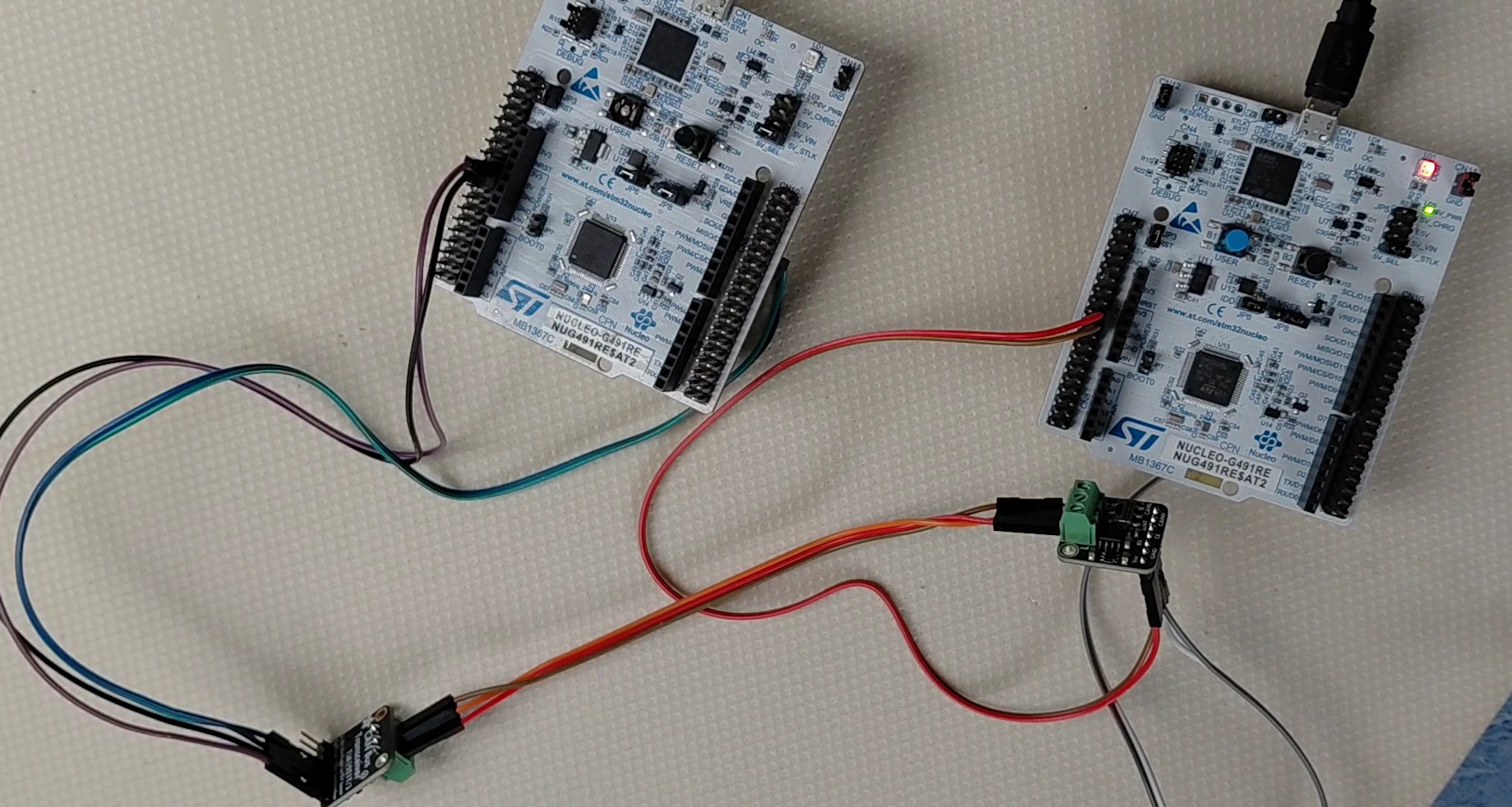
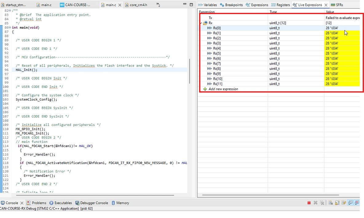
Then, we flash the TX project to one board and the RX project to another. Then, we power both MCU boards and can check the RX buffer in the live expressions. If you are getting the values as in the screenshot below, congratulations! You successfully implemented the CAN Interface. This time, instead of having the Loopback Mode, you are sending data between two nodes. You can be proud of yourself. Next, we will implement CAN Filtering.
STM32 CAN Bus Course
STM32 CAN Filtering
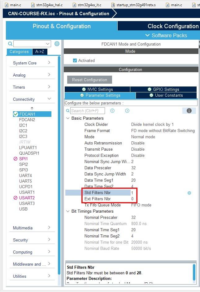
The final important topic is STM32 CAN Filtering. As I mentioned in the first part, Filtering is an essential function of the CAN interface that minimizes computational load on nodes. To configure the filters, first define the number of filters, one for extended and one for standard IDs. In my example, I set the 'Std Filters Nbr' to 1. Then, we can save the file to generate the code.
Then, within the CAN initialization function, define the CAN Filter Structure.
FDCAN_FilterTypeDef filter_config;
Next, we initialize the struct's fields. If the frame passes the filter, I will store it within FIFO0. In my example, I use a dual filter, meaning the frame ID must be either FilterID1 or FilterID2 to pass. Instead, it could be a range filter (ID between FilterID1 and FilterID2) or a classical mask filter (FilterID1 = filter, FilterID2 = mask). In addition, it is vital to configure the global filters.
filter_config.FilterConfig = FDCAN_FILTER_TO_RXFIFO0;
filter_config.FilterID1 = 0x77;
filter_config.FilterID2 = 0x79;
filter_config.FilterIndex = 0;
filter_config.FilterType = FDCAN_FILTER_DUAL;
filter_config.IdType = FDCAN_STANDARD_ID;
if (HAL_FDCAN_ConfigFilter(&hfdcan1, &filter_config) != HAL_OK)
{
/* Filter configuration Error */
Error_Handler();
}
if(HAL_FDCAN_ConfigGlobalFilter(&hfdcan1, FDCAN_REJECT, FDCAN_REJECT, FDCAN_REJECT_REMOTE, FDCAN_REJECT_REMOTE) != HAL_OK)
{
Error_Handler();
}
/* USER CODE END FDCAN1_Init 2 */
Once I configure the filters, I rerun the code. I successfully received the message since the frame's ID the node is sending is 0x77, and it passes the filter. But if I change the conditions, I no longer receive the message.