STM32 PWM Input Mode
Oct 13, 2025
In robotic and embedded programming applications, it is quite important to not only generate but also read PWM signals. A vivid example of it is working with RC Joysticks receivers which became widespread thanks to drones and other unmanned vehicles. It generates PWM signals with varying duty cycles according to the position of the Joystick rods. Therefore, modern microcontrollers can read PWM signals, and STM32 MCUs are no exception. Nevertheless, there is little information about this functionality on the web. This article aims to fill this gap and provide you with clear guidance on STM32 PWM Input Mode.
We will use STM32CubeIDE, the HAL API, and CubeMX to develop our code. The STM32F4 Discovery Board will be our main hardware. In addition, we will use an RC Joystick to test our code.
STM32 PWM Input Mode Timer configuration in CubeMx
Let's dive into configuring the timer for the PWM Input Mode.
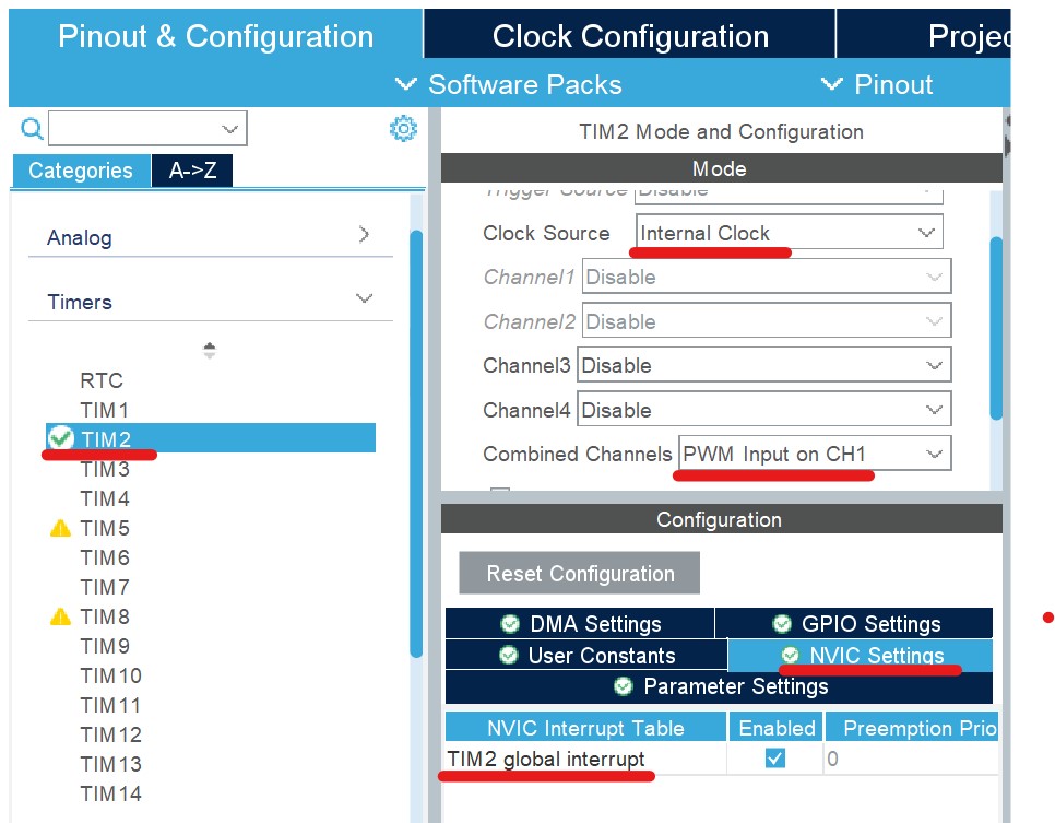
- Among the various timers, we need to choose one to read the PWM signals. In my case, I chose TIM2. We enable it by choosing the Internal Clock as the clock timer. Then, for combined Channels, we set the PWM Input on Ch1. Also, enable the Timer global Interrupts by ticking the box. We can play with other parameters to optimize the code, but for demonstration purposes, we can keep the rest at their default values.
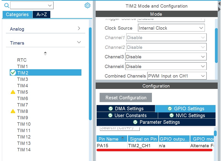
- Then, Open GPIO Settings. There, you will find a pin from which the STM32 MCU will read a PWM signal. If you are using a joystick, connect the receiver's output to this pin. In my case, it is PA15. Finally, we can save the .ioc file and generate the code.
STM32 PWM Input Frequency and Duty Cycle capturing using HAL API
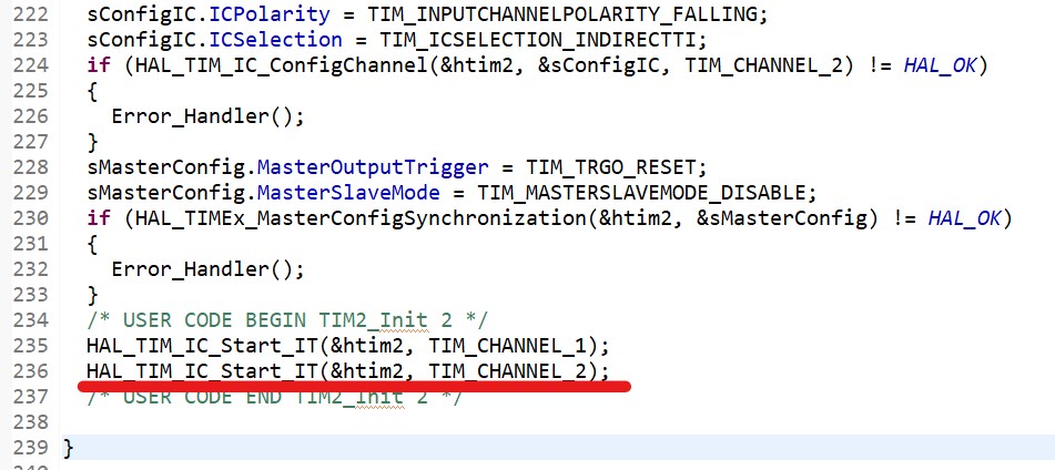
The next thing we need to do is to enable the timer by calling the HAL_TIM_IC_Start_IT function. Two channels of the timer will be responsible for capturing an input PWM signal. So, we call this function twice within the timer configuration function (MX_TIM2_Init in my case).
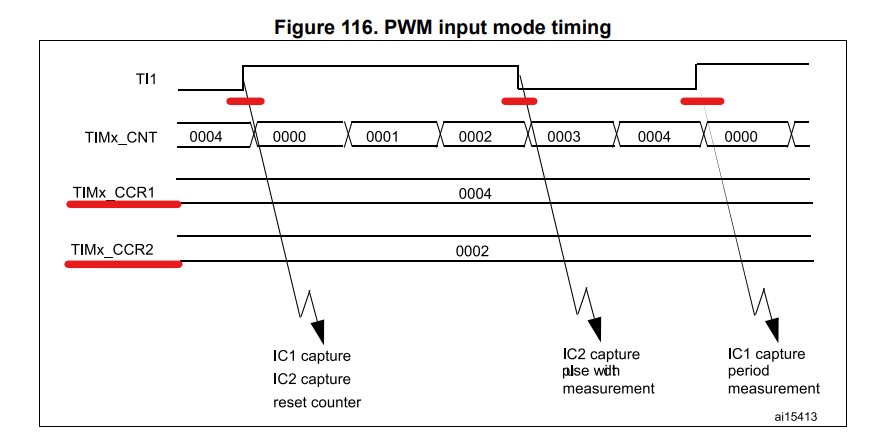
To understand the rest of the code, I would like to deviate from the main topic and talk a little bit about how the microcontroller captures input PWM signals. The picture below demonstrates the working principle of time PWM Input Mode. By capturing the rising edges using channel 1 of the timer, the microcontroller identifies the frequency of the PWM signal (by measuring the time between two consecutive rising edges). Channel 2 detects the falling, which will eventually allow us to obtain the duty cycle of the PWM signal (time between the consecutive rising and falling edges).
If we implement this scheme in our project, we will obtain the following piece of code:
int32_t frequency, duty_cycle;
uint32_t capture_value;
void HAL_TIM_IC_CaptureCallback(TIM_HandleTypeDef *htim)
{
    if(htim ->Channel == HAL_TIM_ACTIVE_CHANNEL_1)
    {
        capture_value = HAL_TIM_ReadCapturedValue(htim, TIM_CHANNEL_1);
	if(capture_value)
	{
	    frequency = SystemCoreClock / (capture_value);
            duty_cycle = 10000 * HAL_TIM_ReadCapturedValue(htim, TIM_CHANNEL_2) /
					capture_value - 750;
        }
     }
}
HAL_TIM_IC_CaptureCallback is invoked whenever the microcontroller captures the rising edge and falling edge of the signal. Then, we check whether it happened in channel 1. If so, we can read the number of ticks by calling HAL_TIM_ReadCapturedValue function. Then, we can read the duty cycle of the PWM signal using the same function, but for channel 2. To get the frequency of the PWM signal, we can use the SystemCoreClock.
To obtain the duty cycle I divided channel 2 captured value by channel 1 captured value. Then, multiply by 10000 and subtract 750. These parameters depend on the frequency of the timer. Tune them to get the best range of the duty cycle value.
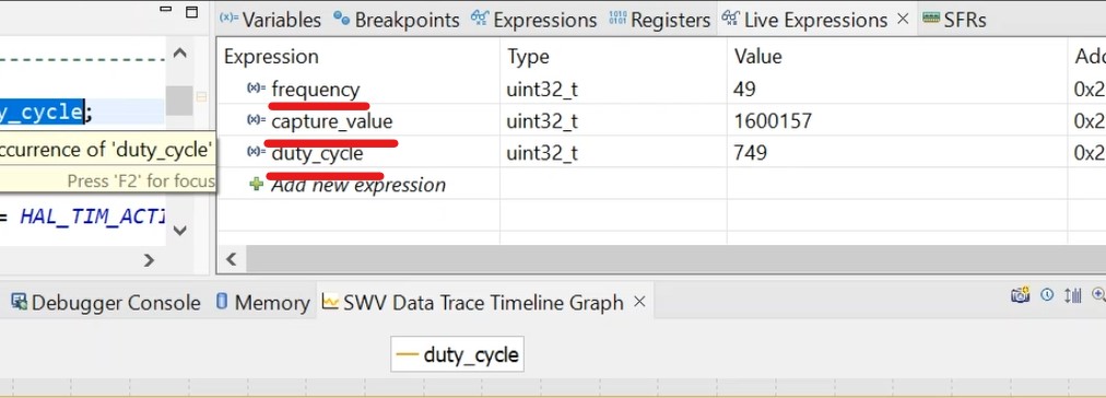
Finally, we can run the code and see how things work using Live Expressions. If you have a joystick, the duty_cycle will change according to the stick's position.
It is worth mentioning that overflow may occur when reading PWM Input signals. In that case, set the prescaler of the timer. You can refer to the following article to get info about the timer prescaler:
Please comment if you have any problems!
STM32 PWM Input Mode Video Tutorial