STM32 Timer Introduction
Oct 13, 2025
The timer is an essential peripheral in microcontrollers. It allows tracking time, generating digital signals, periodically executing code, and much more. At first glance, notions of clock and timer might be confusing. But they are entirely different things. The former is a physical component responsible for synchronizing all microcontroller components. The latter is a peripheral used with other peripherals to execute code periodically and generate digital signals. Let me present the fundamental parameters of the STM32 Timer:
1. The Operating frequency of the timer is the number of ticks it does per second.
2. A prescaler is required to adjust the operating frequency of the timer:
Operating frequency = Clock frequency/ prescaler+1
3. The counter of the timer is a value that tracks the ticks of the Timer. It is incremented according to the timer's frequency. For example, a 1 MHz frequency timer updates the counter a million times per second. From a software point of view, the counter is a 16-bit variable (register) whose rate of change is governed by the timer frequency.
4. Auto-reload. The counter cannot tick to infinity. In STM32 microcontrollers, 16-bit counters are common, meaning they can count up to 65535 (216 − 1) and reset to zero. However, we can set a custom maximum value of the counter using the auto-reload register. If we set the auto-reload to 2000, the counter starts from 0 and reaches 2000. Then, instead of getting incremented further, it starts from zero.
It is also worth mentioning the timer counting modes: upcounting, downcounting, and center-aligned. By default, timers operate in an upcounting mode, starting from zero and incrementing to the auto-reload value. Then it restarts from zero. In the downcounting mode, the timer starts at the auto-reload value and counts down to zero. Then, it resumes from the auto-reload value. The counter starts at 0 and reaches the auto-reload value in center-aligned mode. Afterward, instead of starting from zero, the timer decrements the counter until it reaches zero.
Enabling STM32 Timer in STM32Cubemx
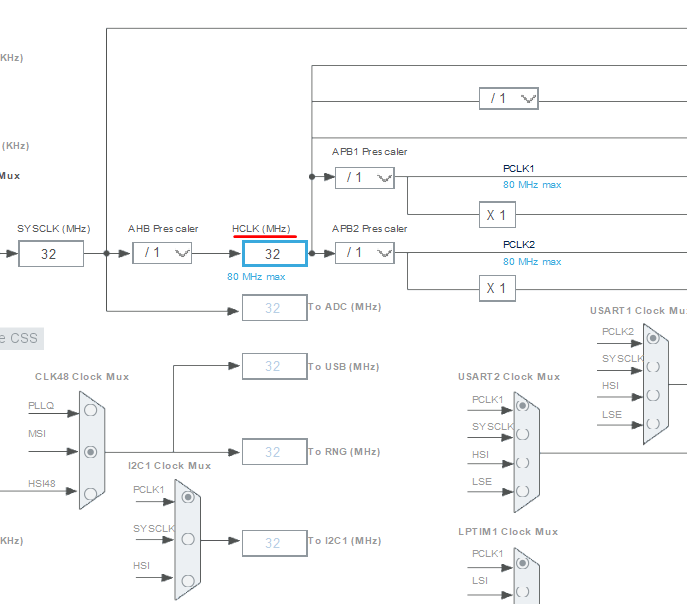
Let’s configure Timer 1 using STM32CubeMX. I will utilize the Nucleo-L412KB STM32 board and configure Timer 1. However, the tutorial can be adapted to other MCUs. In this board, the clock frequency is 32 MHz (HCLK); see the figure below.
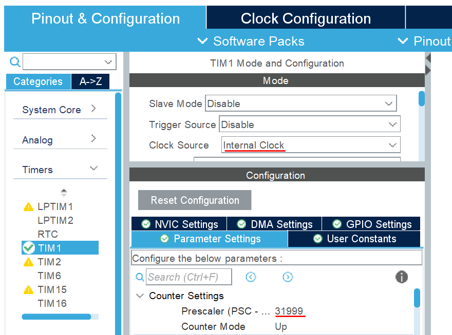
To enable Timer 1, we select the internal clock as the timer's clock source. Also, we need to set the Prescaler to 31999 to achieve a 1 kHz operating frequency, since the HCLK frequency is 32 MHz.
Then, we can generate the code by saving the IOC file. Eventually, we enable the STM32 timer using HAL_TIM_Base_Start(); function. As an argument, we provide a struct variable. We can write this line at the end of the MX_TIM1_Init function.
HAL_TIM_Base_Start(&htim1);Finally, to check how it works, I defined two global variables and wrote the following code within the while loop:
timer_value1 = __HAL_TIM_GET_COUNTER(&htim1);

HAL_Delay(1000);

timer_value2 = __HAL_TIM_GET_COUNTER(&htim1);

HAL_Delay(1000);
, where the _HAL_TIM_GET_COUNTER function provides the Timer’s counter value. In the debug mode, we can monitor timer_value1 and timer_value2 in real time. Since I assign the counter's value to the variables with a 1-second delay, the difference between these variables is 1000 because the Timer ticks 1000 times per second. After all, the Timer's operating frequency is 1 kHz.
You can refer to this article to use the Timer to generate a PWM signal:
STM32 PWM signal generation
In addition, there is a video explaining the key parameters of STM32 Timers.